


12 - 35
12. OPTIONS AND AUXILIARY EQUIPMENT
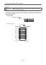
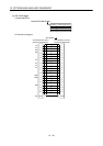
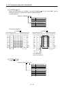
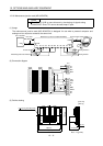
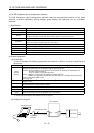
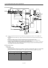
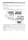
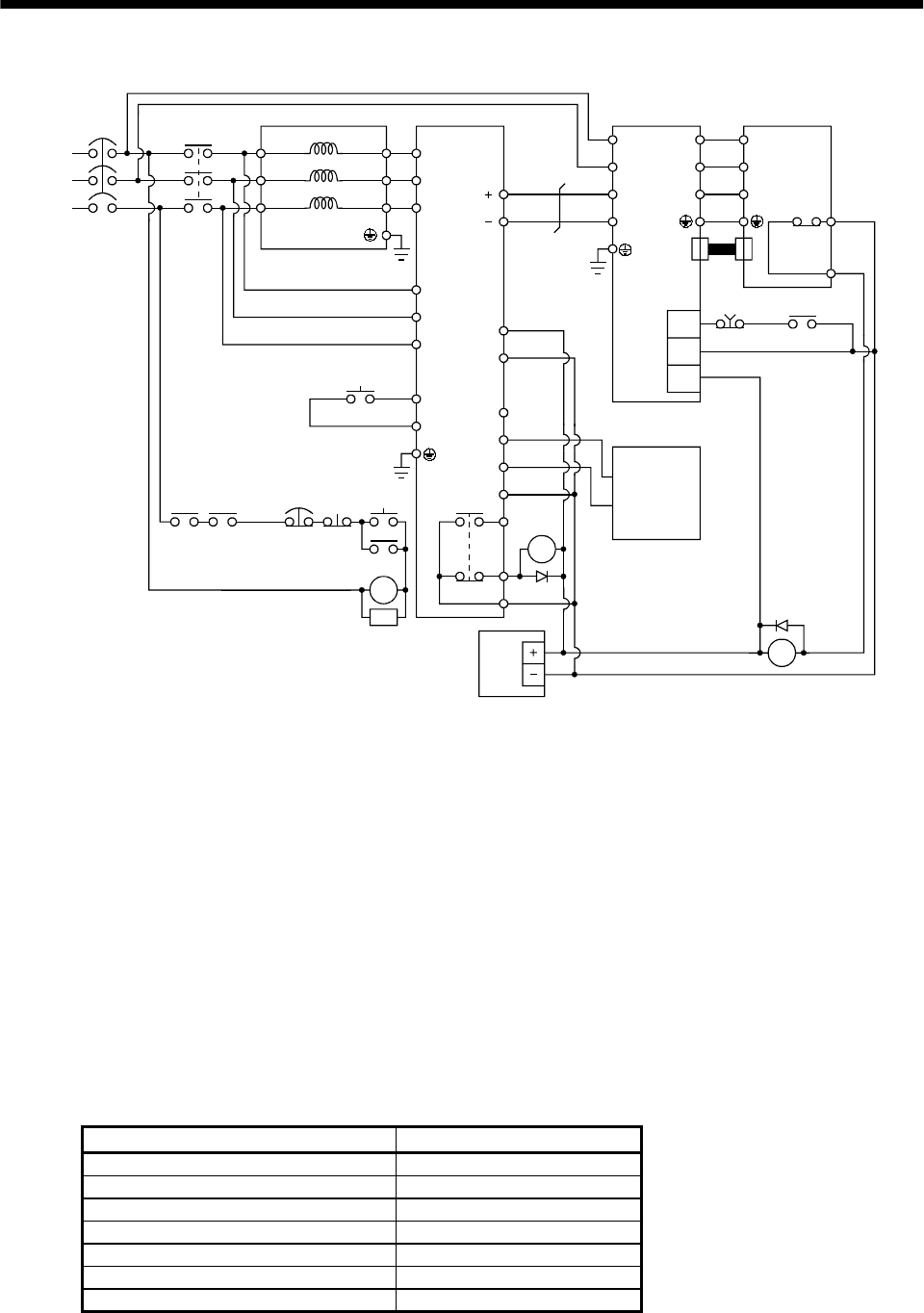
(2) Connection diagram
RA1
EM1
C
B
R/L
11
Three-phase
200 to 230VAC
S/L
21
T/L
31
R2/L
1
S2/L
22
R2/L
12
T2/L
32
S2/L
2
N/L
P24
SD
RDYB
RDYA
RSO
SE
A
P/L
T2/L
3
R/L
11
S/L
21
T/MC1
RES
SD
L
11
L
21
P
N
SG
COM
U
V
W
EM1
(Note 1)
RA1
RA2
24VDC
power
supply
U
V
W
Thermal
relay
0HS2
0HS1
CN2
MC
NFB
FR-CVL FR-CV
MC
RA1 RA2
EM1
OFF
ON
RESET
SK
MC
Servo motorServo amplifier
Servo system
controller
(Note 5)
(Note 2)
(Note 3)
(Note 4)
(Note 1)(Note 1)
(Note 1)
Note 1. Configure a sequence that will shut off main circuit power at an emergency stop or at FR-CV or servo amplifier alarm
occurrence.
2. For the servo motor with thermal relay, configure a sequence that will shut off main circuit power when the thermal relay
operates.
3. For the servo amplifier, configure a sequence that will switch the servo on after the FR-CV is ready.
4. For the FR-CV, the RS0 signal turns off when it is put in a ready-to-operate status where the reset signal is input.
Configure a sequence that will make the servo inoperative when the RS0 signal is on.
5. Configure a sequence that will make a stop with the emergency stop input of the servo system controller if an alarm occurs
in the FR-CV. When the servo system controller does not have an emergency stop input, use the forced stop input of the
servo amplifier to make a stop as shown in the diagram.
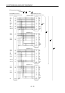
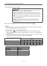
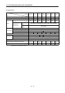
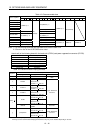
(3) Wires used for wiring
(a) Wire sizes
1) Across P-P, N-N
The following table indicates the connection wire sizes of the DC power supply (P, N terminals)
between the FR-CV and servo amplifier. The used wires are based on the 600V vinyl wires.
Total of servo amplifier capacities [kW] Wires[mm
2
]
1 or less 2
23.5
55.5
78
11 14
15 22
22 50