


3 - 29
3. SIGNALS AND WIRING
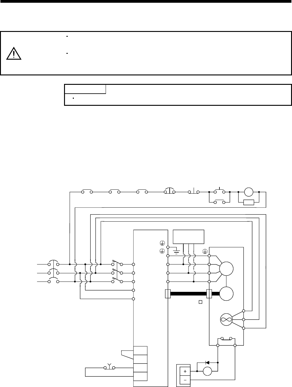
3.12 Power line circuit of the MR-J2S-11KB to MR-J2S-22KB
CAUTION
When the servo amplifier has become faulty, switch power off on the amplifier
power side. Continuous flow of a large current may cause a fire.
Switch power off at detection of an alarm. Otherwise, a regenerative brake
transistor fault or the like may overheat the regenerative brake resistor, causing a
fire.
POINT
The power-on sequence is the same as in Section 3.5.3.
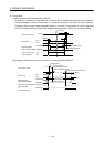
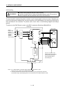
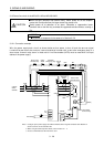
3.12.1 Connection example
Wire the power supply/main circuit as shown below so that power is shut off and the servo-on signal
turned off as soon as an alarm occurs, a servo forced stop is made valid, a controller emergency stop, or a
servo motor thermal relay alarm is made valid. A no-fuse breaker (NFB) must be used with the input
cables of the power supply.
(Note)
Alarm
RA1
Controller
emergency stop
RA2
L
1
L
2
L
3
L
11
L
21
VDD
COM
EM1
SG
Servo amplifier
CN2
U
V
W
U
V
W
Dynamic
break
Servo motor
HA-LFS series
M
Encoder
BU
Fan
RA3
24VDC
power supply
MR-JHSCBL M
cable
BV
BW
MC
SK
ON
MC
OFF
Forced
stop
Servo motor
thermal relay
RA3
NFB MC
Forced stop
OHS2OHS1
Servo motor
thermal relay
(Note3)
3-phase
200 to
230VAC
(Note 2)
Note: 1. Configure up the power supply circuit which switches off the magnetic contactor after detection of
alarm occurrence on the controller side.
2. When using the external dynamic break, refer to section 12. 1. 4.
3. There is no BW when the HA-LFS11K2 is used.