


15
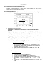
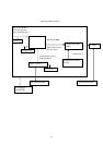
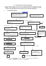
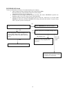
6. A). Interface-Board Trouble-Shooting chart
*Use the PC Win 98 white pattern, with some icon on it, and Change the Resolution to 640x480 60 Hz / 31 KHz
**NOTICE : The free-running freq. of our system is 48 KHz / 60 Hz, so we recommend to use another
resolution to do trouble shooting, this trouble shooting is proceed with 640x480 @60Hz 31Khz
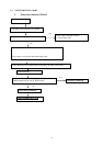
I. NO SCREEN APPEAR
Note: 1. if Replace “MAIN-BOARD” , Please re-do “DDC-content” programmed & “WHITE-Balance”.
2. if Replace “ INVERTER” only, Please re-do “ WHITE-Balance”
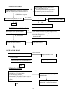
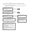
Disconnected the Signal cable( Loose the
Signal cable ),Is the screen show “Cable Not
Connected” ?
Connected the Signal cable again,
Check LED status.
No
,
nothin
g
is show
Yes, there have OSD show
Connected the Signal cable again,
Check LED status.
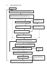
Check the Wire-Harness from CN601,CN602
was tight enough?,
check the Wire connection to panel side too
OK,Wire tight enough
Led Green
Check Panel-Power Circuit Block
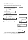
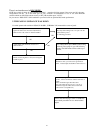
Check U200 Data-output Block
OK,Panel Power OK
Replace Inverter and Check
Inverter control relative circuit
Re-do White balance adjust
OK, U200 data OK
Check Power switch is in Power-on
status , and check if Power switch had
been stuck ?
Measured RGB (r200,r201,r202) H,V Input at U401
p
in 9
,
4
,
was there have si
g
nal ?
Measured Oscillator Block
Oscillator U201 & Crystal X300
Check communication pin between U200 &
MCU pin 2,6,7. , is it have transition?
Led Oran
g
e
Replace U200 (Gmzan1)
OK
,
Ke
y
board no stuc
k
OK
,
in
p
ut Normal
OK
,
clock normal
OK
,
Mcu have transition
Replace U302 (MCU)
& check Reset pin 10
must be change from High to
low when first AC power plug-
in
NG
,
no transition
Led oran
g
e
OK
OK
R
ep
la
ce
M
CU
Led Green
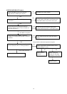
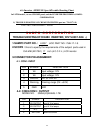
Measured Input DC-voltage ( J1)= 12 V?
Measured U305 AIC 1084 pin 2 = 3.3V?
Measured U904 LT1117 pin 2= 3.3V?
Yes
,
all DC level exist
Check Correspondent component.
Is there any shortage or cold solder?
DC-Power Part
Check Correspondent
component short/open
( Protection Diode )
and Signal cable
bad ?
NG