


40
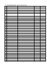
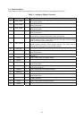
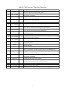
Table 2 : Host Interface (HIF) / External On-Screen Display
PIN # Name I/O Description
98 HFS I
Host Frame Sync. Frames the packet on the serial channel.
103 HCLK I
Clock signal input for the 3-wire serial communication.
99 HDATA I/O
Data signal for the 3-wire serial communication.
100 RESETn I
Resets the gmZAN1 chip to a known state when low.
101 IRQ O
Interrupt request output.
115 OSD-HREF O
HSYNC output for an external OSD controller chip.
116 OSD-VREF O
VSYNC output for an external OSD controller chip.
117 OSD-Clk O
Clock output for an external OSD controller chip.
118 OSD-Data0 I
Data input 0 from an external OSD controller chip.
119 OSD-Data1 I
Data input 1 from an external OSD controller chip.
120 OSD-Data2 I
Data input 2 from an external OSD controller chip.
121 OSD-Data3 I
Data input 3 from an external OSD controller chip.
122 OSD-FSW I
External OSD window display enable. Displays data from external OSD
controller when high.
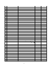
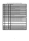
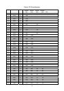
123 MFB11 I/O
Multi-Function Bus 11. One of twelve multi-function signals MFB[11:0].
124 MFB10 I/O
Multi-Function Bus 10. One of twelve multi-function signals MFB[11:0].
102 MFB9 I/O
Multi-Function Bus 9. One of twelve multi-function signals MFB[11:0].
Also used as HDATA3 in a 4-bit host interface configuration.
104 MFB8 I/O
Multi-Function Bus 8. One of twelve multi-function signals MFB[11:0].
Also used as HDATA2 in a 4-bit host interface configuration.
105 MFB7 I/O
Multi-Function Bus 7. One of twelve multi-function signals MFB[11:0].
Also used as HDATA1 in a 4-bit host interface configuration.
106 MFB6 I/O
Multi-Function Bus 6. One of twelve multi-function signals MFB[11:0].
Internally pulled up. When externally pulled down (sampled at reset ) the host
interface is configured for 4 bits wide. In this configuration, MFB9:7 are used as
HDATA 3:1.
107 MFB5 I/O
Multi-Function Bus 5 One of twelve multi-function signals MFB[11:0].
Internally pulled up. When externally pulled down (sampled at reset ) the chip
uses an external crystal resonator across pins 141 and 142, instead of an
oscillator.
109 MFB4 I/O
Multi-Function Bus 4. One of twelve multi-function signals MFB[11:0].
110 MFB3 I/O
Multi-Function Bus 3. One of twelve multi-function signals MFB[11:0].
111 FMB2 I/O
Multi-Function Bus 2. One of twelve multi-function signals MFB[11:0].
112 MFB1 I/O
Multi-Function Bus 1. One of twelve multi-function signals MFB[11:0].
113 MFB0 I/O
Multi-Function Bus 0. One of twelve multi-function signals MFB[11:0].