


52
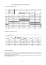
The display start/end registers store the first and the last pixels/lines of the last frame that have RGB data above a
programmed threshold.
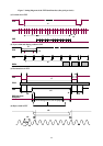
The reference point of the STM block is the same as that of the source timing generator (STG) block:
z The first pixel: the pixel whose SCLK rising edge sees the transition of the HSYNC polarity from low to high.
z The first line: the line whose HSYNC rising edge sees the transition of the VSYNC polarity from low to high.
The CRC data and the line data are used to detect a test pattern image sent to the gmZAN1 input port.
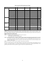
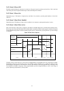
2.4.2 IRQ Controller
Some input timing conditions can cause the gmZAN1 chip to generate an IRQ. The IRQ-generating conditions are
programmable, as given in the following table.
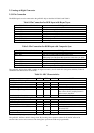
Table 12. IRQ-Generation Conditions
IRQ Event Remark
Timing Event One of the three events:
z Leading edge of Vsync input,
z Panel line count (the line count is programmable),
z Every 10ms
Only one event may be selected at a time.
Timing Change Any of the following timing changes:
z Sync loss,
z DDS tracking error beyond threshold,
z Horizontal/vertical timing change beyond threshold
Threshold values are programmable.
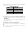
Reading the IRQ status flags will not affect the STM registers.
Note that if a new IRQ event occurs while the IRQ status register is being read, the IRQ signal will become inactive
for minimum of one TCLK period and then get re-activated. The polarity of the IRQ signal is programmable.
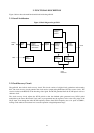
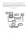
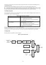
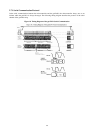
2.5 Data Path
The data path block of gmZAN1 is shown in Figure 6.
Figure 6. gmZAN1 Data Path
Sampled Data
(or from
pattern
generator
Scaling
Filter
Gamma
Table
RGB
Offset
Panel
Data
Dither
Background
Color
Internal
OSD
External
OSD
1
0
S
1
0
S
1
0
S
8 8 10
8 or 6
Panel
Data
8 or 6