


61
2.8.1 OSD Color Map
Both the internal and external OSD display use a 16 location SRAM block for the color programming. Each color
location is a twelve-bit value that defines the upper four bits of each of the 8 bit Red, Blue and Green color
components as follows:
z D3:0 Blue; D7:4 of blue component of color
z D7:4 Green; D7:4 of green component of color
z D11:8 Red; D7:4 of red component of color
To extend the 4-bit color value programmed to the full 8 bits the following rule is applied: if any of the upper four
color bits are a “1”, then R (G, B) data 3:0=1111b, otherwise R (G, B) data 3:0=0000b
2.8.2 On-Chip OSD Controller
The internal OSD uses a block of SRAM of 1536x12 bits and a ROM of 1024x12 bits. The SRAM is used for both the
font data and the character-codes while the ROM is used to store the bit data for 56 commonly used characters. The
font data is for 12 pixel x 18 line characters, one bit per pixel. The font data starts at address zero. The character-codes
start at any offset (with an address resolution of 16) that is greater than the last location at which font data has been
written . It is the programmer’s responsibility to ensure that there is no overlap between fonts and character-codes.
This implementation results in a trade-off between the number of unique fonts on-screen at any one time and the total
number of characters displayed. For example, one configuration would be 98 font maps (56 fonts in ROM and 42
fonts in SRAM) and 768 characters (e.g. in a 24x32 array).
The on-chip OSD of the gmZAN1 can support a portrait mode (in which the LCD monitor screen is rotated 90
degrees). In this portrait mode, all the fonts must be loaded in the SRAM, because the ROM stores fonts for a
landscape mode (typical orientation) only. The font size in the portrait mode is 12 pixels by 12 lines. As is the case in
landscape mode, the SRAM is divided into a font storage area and a character code storage area. For example, 64
fonts can be stored in RAM and an OSD window of 768 characters (such as 24x32) can still be displayed.
The first address of SRAM to be read for the first character displayed (upper left corner of window)is also
programmable, with an address resolution of 16 (8-bits as the top bits of the 12-bit SRAM address). The character-
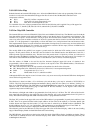
code is a 12-bit value used as follows:
z D6:0 font-map select, this is the top seven bits of the address for the first line of font bits
z D8:7 Background color, 00=bcolor0, 01=bcolor1, 10=bcolor2, 11=transparent background
z D10:9 Foreground color (0, 1, 2 or 3)
z D11 Blink enable if set to 1, otherwise no blink
Although the OSD color map has room for sixteen colors, only seven are used by the internal OSD: three background
colors and four foreground colors.
The blink rate is based on either a 32 or 64 frame cycle and the duty cycle may be selected as 25/75/50/50% or
75/25%. The 2-bit foreground and background attributes directly select the color (there is no indirect “look-up”, i.e.
there is no TMASK function). The 2560 addresses of the ROM/SRAM are mapped as 10 segments of 256 contiguous
addresses each, to the OSD memory page of 100h-1FFh in the host interface. A 4-bit register value selects the
segment to map to the host R/W page.
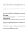
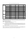
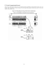
The character cell height and width are programmable from 5-66 pixels or 2-65 lines. The X/Y offset of the font bit-
map upper-left pixel relative to the upper-left pixel of the character cell is also programmable from 0-63 (pixels or
lines). The OSD window height and width in characters/rows is programmable from 1-64.
The Start X/Y position for the upper left corner of the OSD window is programmable (in panel pixels and lines) from
0-2047. There is an optional window border (equal width on all four sides of the window) or a window shadow (the
window bottom and right side) the border is a solid color that is selected by an SRAM location as RGB444. The
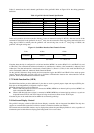
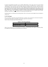
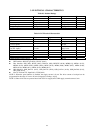
border width may be set as 1, 2, 4 or 8 pixels/lines. These parameters are summarized in Figure 12 and Table 16.
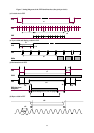
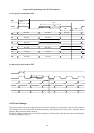
The Font Data D11:0 for each line is displayed with bit D11 first (leftmost) and D0 last.
The reference point for the OSD start is always the upper left corner of the Panel display, which is the start (leading
edge) of Panel Display Enable for both Horizontal and Vertical timing.
The OSD Window start position sets the location of the first pixel of the OSD to display, including any border. That is;
if the border is enabled, the start of the character display of the OSD is offset from the OSD start position by the
width/height of the border.