


49
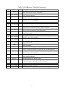
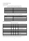
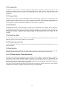
The table below summarizes the characteristics of the clock recovery circuit.
Table 7. Clock Recovery Characteristics
Minimum Typical Maximum
SCLK Frequency 10MHz 135 MHz
Sampling Phase Adjustment 0.5 ns/step, 64 steps
Patented digital clock synthesis technology makes the gmZAN1 clock circuits very immune to temperature/voltage
drift.
2.2.1 Sampling Phase Adjustment
The ADC sampling phase is adjusted by delaying the Hsync input at the programmable delay cell inside the gmZAN1.
The delay value can be adjusted in 64 steps, 0.5 ns/step. The accuracy of the sampling phase is checked by the
gmZAN1 and the “score” can be read in a register. This feature will enable accurate auto-adjustment of the ADC
sampling phase.
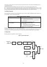
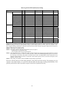
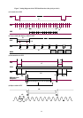
2.2.2 Source Timing Generator
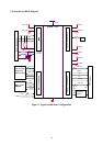
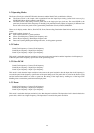
The STG module defines a capture window and sends the input data to the data path block. The figure below shows
how the window is defined.
For the horizontal direction, it is defined in SCLKs (equivalent to a pixel count). For the vertical direction, it is
defined in lines.
All the parameters in the figure that begin with “Source” are programmed into the gmZAN1 registers.
Note that the vertical total is solely determined by the input.
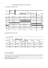
The reference point is as follows:
z The first pixel of a line: the pixel whose SCLK rising edge sees the transition of the HSYNC polarity from low
to high.
z The first line of a frame: the line whose HSYNC rising edge sees the transition of the VSYNC polarity from low
to high.
The gmZAN1 also supports the use of analog composite sync and digital sync signals as described in Section 2.3.2
Figure 5. Capture Window
Capture Window
Source Vertical Total (lines)
Source
Hstart
Source Height
Reference
Point
Source
Vstart
Source Horizontal Total (pixels)
Source Width