


50
2.3 Analog-to-Digital Converter
2.3.1 Pin Connection
The RGB signals are to be connected to the gmZAN1 chip as described in Table 8 and Table 9.
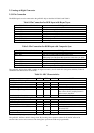
Table 8. Pin Connection for RGB Input with Hsync/Vsync
GmZAN1 Pin Name (Pin Number) CRT Signal Name
Red+(#95) Red
Red- (#94) N/A (Tie to Analog GND for Red on the board)
Green+(#91) Green
Green- (#90) N/A (Tie to Analog GND for Green on the board)
Blue+(#87) Blue
Blue- (#86) N/A (Tie to Analog GND for Blue on the board)
HSYNC/CS (#150) Horizontal Sync
VSYNC (#148) Vertical Sync
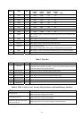
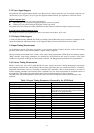
Table 9. Pin Connection for RGB Input with Composite Sync
GmZAN1 Pin Name (Pin Number) CRT Signal Name
Red+(#95) Red
Red- (#94) N/A (Tie to Analog GND for Red on the board)
Green+(#91) Green
When using Sync-On-Green this signal also carries the sync pulse.
Green- (#90) N/A (Tie to Analog GND for Green on the board)
Blue+(#87) Blue
Blue- (#86) N/A (Tie to Analog GND for Blue on the board)
HSYNC/CS (#150) Digital composite sync. Not applicable for Sync-On-Green
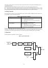
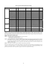
The gmZAN1 chip has three ADC’s (analog-to-digital converters), one for each color (red, green, and blue). Table 10
summarizes the characteristics of the ADC.
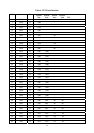
Table 10. ADC Characteristics
MIN TYP MAX NOTE
RGB Track & Hold Amplifiers
Band Width 160MHz
Settling Time to 1/2% 8.5ns Full Scale Input = 0.75V, BW=160MHz(*)
Full Scale Adjust Range @ R,G,B Inputs 0.45V 0.95V
Full Scale Adjust Sensitivity +/-1 LSB Measured @ ADC Output (**)
Zero Scale Adjust Range For a larger DC offset from an external
video source, the AC coupling feature is
used to remove the offset.
Zero Scale Adjust Sensitivity +/-1 LSB Measured @ ADC Output
ADC+RGB Track & Hold Amplifiers
Sampling Frequency (fs) 20MHz 110MHz
DNL +/- 0.9LSB fs = 80 MHz
INL +/- 1.5LSB fs = 80 MHz
Channel to Channel Matching +/- 0.5LSB
Effective Number of Bits (ENOB) 7 Bits fin = 1MHz, fs=80 MHz Vin= -1db below
full scale=0.75V
Power Dissipation 400mW fs=110 MHz, Vdd=3.3V
Shut Down Current 100uA
(*) Guaranteed by design (**) Independent of full scale R,G,B input
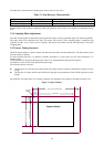
The gmZAN1 ADC has a built-in clamp circuit. By inserting series capacitors (about 10 nF) the DC offset of an
external video source can be removed. The clamp pulse position and width are programmable.