


56
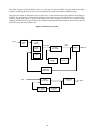
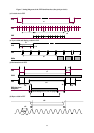
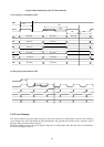
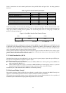
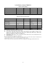
Figure 8. Data latch timing of the TFT Panel Interface
(a) Two pixel per clock mode in TFT
(b) One pixel per clock mode in TFT
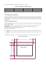
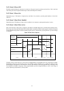
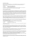
2.6.2 Power Manager
LCD panels require logic power, panel bias power, and control signals to be sequenced in a specific order, otherwise
severe damage may occur and disable the panel permanently. The gmZAN1 has a built in power sequencer (Power
Manager) that prevents this kind of damage.
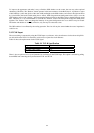
The Power Manager controls the power up/down sequences for LCD panels within the four states described below.
See the timing diagram Figure 9.
G0,(N:0)
R0,(N:0)
PCLK
R3,(N:0)
t17
ER
OB
t16
R4,(N:0)
t13
B0,(N:0)
t16
R2,(N:0)
B2,(N:0)
t14
EG
G1,(N:0) G3,(N:0)
OG
t15
B1,(N:0)
PDE
R1,(N:0)
OR
G2,(N:0)
B3,(N:0)
EB