


39
1.3 Pin Description
Unless otherwise stated, unused input pins must be tied to ground, and unused output pins left open.
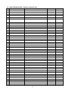
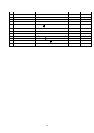
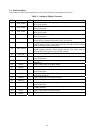
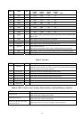
Table 1 : Analog-to-Digital Converter
PIN # Name I/O Description
77 ADC_VDD2
Digital power for ADC encoding logic. Must be bypassed with 0.1uF capacitor to
pin 78 (ADC_GND2)
78 ADC_GND2
Digital GND for ADC encoding logic. Must be directly connected to the digital
system ground plane.
79 ADC_VDD1
Digital power for ADC clocking circuit. Must by passed with 0.1uF capacitor to
pin 80 (ACD_GND1).
80 ADC_GND1
Digital GND for ADC clocking circuit. Must be directly connected to the digital
system ground plane.
81 SUB_GNDA
Dedicated pin for substrate guard ring that protects the ADC reference system.
Must be directly connected to the analog system ground plane.
82 ADC_GNDA
Analog ground for ADC analog blocks that are shared by all three channels.
Includes bandgap reference, master biasing and full scale adjust. Must be directly
connected to analog system ground plane.
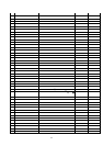
84 ADC_VDDA
Analog power for ADC analog blocks that are shared by all three channels.
Includes bandgap reference, master biasing and full scale adjust. Must be
bypassed with 0.1uF capacitor to pin 82 (ADC_GNDA).
83 Reserved
For internal testing purpose only. Do not connect.
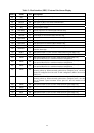
85 ADC_BGNDA
Analog ground for the blue channel. Must be directly connected to the analog
system ground plane.
88 ADC_BVDDA
Analog power for the blue channel. Must be bypassed with 0.1uF capacitor to pin
85(BGNDA).
86 BLUE- I
Negative analog input for the Blue channel.
87 BLUE+ I
Positive analog input for the Blue channel.
89 ADC_GGNDA
Analog ground for the green channel. Must be directly connected to the analog
system ground plane.
92 ADC_GVDDA
Analog power for the green channel. Must be bypassed with 0.1uF capacitor to
pin 89 (ADC_GGNDA).
90 GREEN- I
Negative analog input for the Green channel.
91 GREEN+ I
Positive analog input for the Green channel.
93 ADC_RGNDA
Analog ground for the red channel. Must be directly connected to the analog
system ground plane.
96 ADC_RVDDA
Analog power for the red channel. Must be bypassed with 0.1uF capacitor to pin
93 (ADC_RGNDA).
94 RED- I
Negative analog input for the Red channel.
95 RED+ I
Positive analog input for the Red channel.