


51
2.3.2 Sync. Signal Support
The gmZAN1 chip supports digital separate sync (Hsync/Vsync), digital composite sync, and analog composite sync
(also known as sync-on-green). All sync types are supported without external sync separation / extraction circuits.
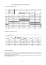
Digital Composite Sync
The types of digital composite sync inputs supported are:
z OR/AND type: No Csync pulses toggling during the vertical sync period
z XOR type: Csync polarity changes during the vertical sync period
The gmZan1 provides enough sync status information for the firmware to detect the digital composite sync type.
Sync-On-Green (Analog Composite Sync)
The voltage level of the sync tip during the vertical sync period can be either –0.3V or 0V
2.3.3 Display Mode Support
A mode calculation utility (MODECALC.EXE) provided by Genesis Microchip may be run before compilation of the
firmware to determine which input modes can be supported. Refer to firmware documents for more details.
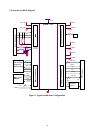
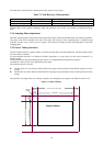
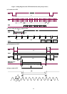
2.4 Input Timing Measurement
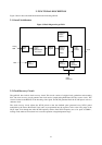
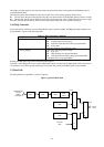
As described in section 2.2.2 above, input data is sent from the analog-to-digital converter to the source timing
generator (STG) block. The STG block defines a capture window (Figure5).
The input timing measurement block consists of the source timing measurement (STM) block and interrupt request
(IRQ) controller. Input timing parameters are measured by the STM block and stored in registers. Some input
conditions will generate an IRQ to an external micro-controller. The IRQ generating conditions are programmable.
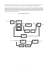
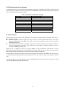
2.4.1 Source Timing Measurement
When it receives the active CRT signal (R,G,B and Sync signals) the Source Timing Measurement unit begins
measuring the horizontal and vertical timing of the incoming signal using the sync signals and TCLKi as a reference.
Horizontal measurement occurs by measuring a minimum and a maximum value for each parameter to account for
TCLKi sampling granularity. The measured value is updated every line. Vertical parameters are measured in terms of
horizontal lines. The trailing edge of the Hsync input is used to check the polarity of the Vsync input.
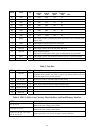
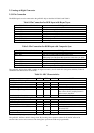
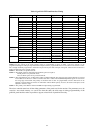
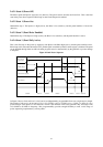
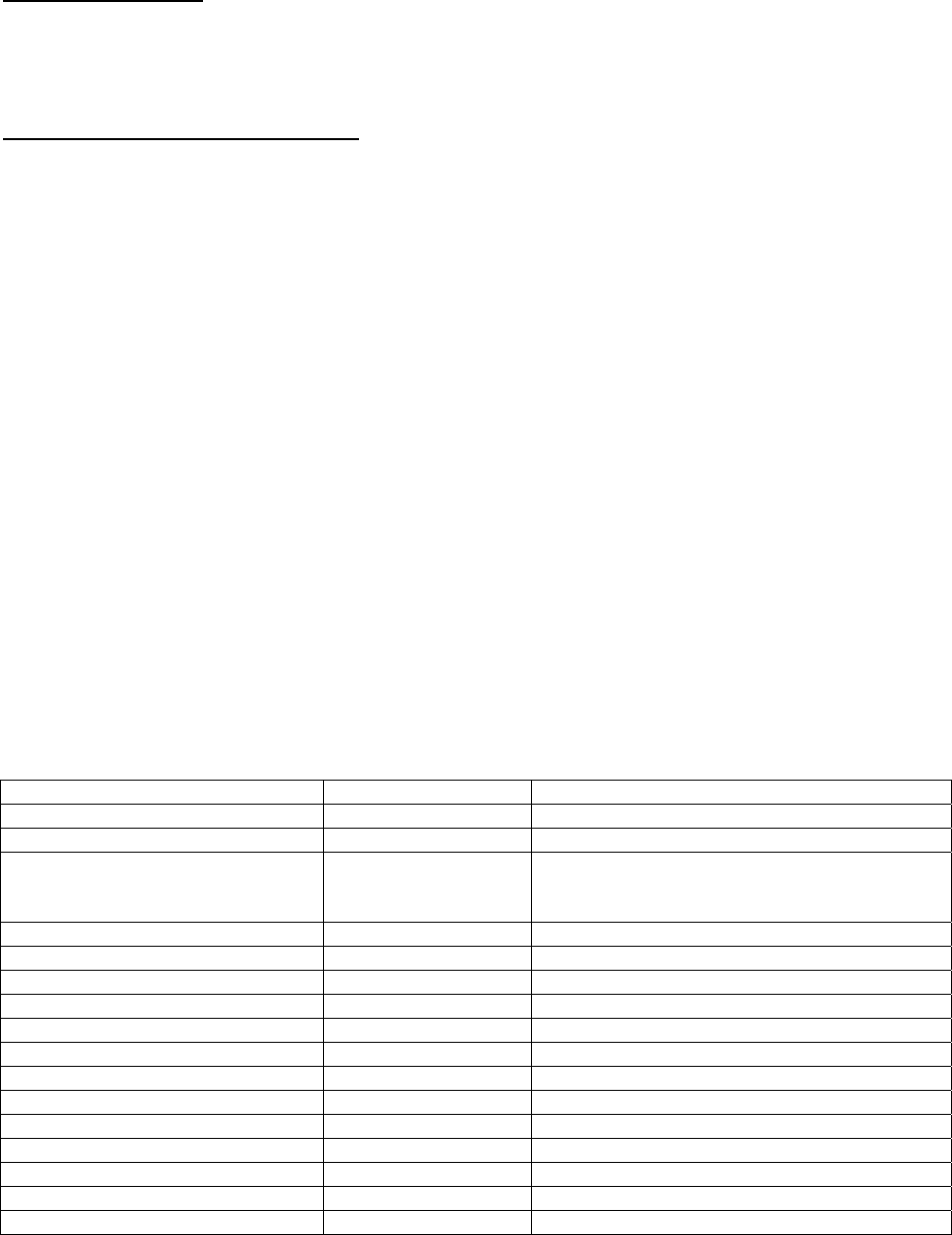
The table below lists all the parameters that may be read in the source timing measurement (STM) registers of the
gmZAN1.
Table 11. Input Timing Parameters Measured by the STM Block
Parameter Unit Updated at:
HSYNC Missing N/A Every 4096 TCLKs and every 80ms (2-bits)
VSYNC Missing N/A Every 80ms
HSYNC/VSYNC Timing Change N/A When the horizontal period delta or the vertical
p
eriod delta to the previous line / frame exceeds the
threshold value (programmable).
HSYNC Polarity Positive/Negative After register read
VSYNC Polarity Positive/Negative Every frame
Horizontal Period Min/Max TCLKs and SCLKs After register read
HSYNC High Period Min/Max TCLKs After register read
Vertical Period Lines Every frame
VSYNC High Period Lines Every frame
Horizontal Display Start SCLKs Every frame
Horizontal Display End SCLKs Every frame
Vertical Display Start Lines Every frame
Vertical Display End Lines Every frame
Interlaced Input Detect N/A Every frame
CRC Data/Line Data N/A Every frame
CSYNC Detect N/A Every 80ms