


48
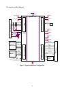
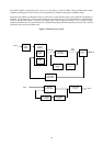
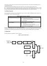
The SCLK frequency (1/SCLK period) can be set to the range of 10-to-135 MHz. Using the DDS (direct digital
synthesis) technology the clock recovery circuit can generate any SCLK clock frequency within this range.
The pixel clock (DCLK or destination clock) is used to drive a panel when the panel clock is different from SCLK (or
SCLK/2). It is generated by a circuit virtually identical to the clock recovery circuit. The difference is that DCLK is
locked to SCLK while SCLK is locked to the Hsync input. DCLK frequency divided by N is locked to SCLK
frequency divided by M. The value M and N are calculated and programmed in the register by firmware. The value M
should be close to the Source Htotal value.
Figure 4. Clock Recovery Circuit
Sample
Phase
Delay
DDS Digital
Clock
Synthesis
Course
Adjust
Fine
Adjust
Analog
PLL & VCO
Clock
Divider
÷ n
PLL
Divider
÷
m
Prescaler
÷ 2 (or 1)
Source
Horizontal
Total Divider
Hsync
DDS Output
VCO
Out
p
ut
SCLK
Analog
PLL & VCO
Post Scale
÷ 2 (or 1)
PLL Divider
÷
n(2to8)
PLL Divider
÷
2 (or 1)
RCLK
TCLK