


60
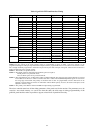
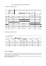
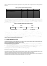
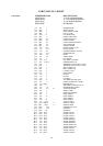
Table 15 summarizes the serial channel specification of the gmZAN1. Refer to Figure 10 for the timing parameter
definition.
Table 15. gmZAN1 Serial Channel Specification
Parameter Min. Typ. Max.
Word Size (Instruction and Data) --- 12 bits ---
HCLK low to HFS high (t1) 100 ns
HFS low to HCLK inactive (t2) 100 ns
HDATA Write to Read Turnaround Time (t3) 1 HCLK cycle 1 HCLK cycle
HCLK cycle (t4) 100 ns
Data in setup time (t5) 25 ns
Data in hold time (t6) 25 ns
Data out valid (t7) 5 ns 10
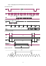
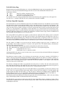
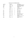
In the read operation, the microcontroller (Initiator) issues an instruction lasting 12 HCLKs. After the last bit of the
command is transferred to the gmZAN1 on the 12
th
clock, the microcontroller must stop driving data before the next
rising edge of HCLK at which point the gmZAN1 will start driving data. At the 13
th
rising edge of HCLK, the
gmZAN1 will begin driving data.
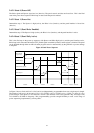
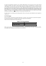
Figure 11. Serial Host Interface Data Transfer Format
2 bits 10 bits 12 bits
Command Address Data
Command: 01 Write 00 = Read 1x = Reserved
Note that when the chip is configured for a 4-bit host interface, MFB9:7 are used as HDATA 3:1 and HDATA is used
as HDATA0. The command and address information are transferred as Address 1:0+Command1:0, Address5:2 and
Address9:6. The data information is transferred as Data3:0,Data 7:4, Data 11:8. Thus, in this mode the HDATA pin
carries Command0, Address2, Address6, Data0, Data4 and Data8.
On the gmZAN1 reference design board, the microcontroller toggles the HCLK and HDATA lines under program
control. Genesis Microchip provides API calls to facilitate communication between the microcontroller and the
gmZAN1. Refer to the API reference manual for details.
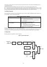
2.7.2 Multi-Function Bus (MFB)
The Multi-Function Bus provides additional 12 pins that are used as general purpose input and output (GPIO) pins.
Each pin can be independently configured as input or output.
MFB pins 9 through 5 have special functions:
z When a 10K ohm pull-down resistor is connected to MFB6 (MFB6 has an internal pull-up resistor) MFB9:7 are
used as host data bits HDATA3:1.
z When a 10K ohm pull-down resistor is connected to MFB5 (MFB5 has an internal pull-up resistor) a crystal can
be placed between XTAL and TCLK instead of using an external oscillator for the TCLK input.
Note that all pins on the multi-function bus MFB11:0 are internally pulled-up.
2.8 On-Screen Display Control
The gmZAN1 chip has a built-in OSD (On-Screen Display) controller with an integrated font ROM. The chip also
supports an external OSD controller for monitor vendors to maintain a familiar user interface.
The internal and external OSD windows may be displayed anywhere the panel Display Enable is active, regardless of
whether the panel would otherwise display panel background color or active data.