


62
To improve the appearance and make it easy to find the OSD window on the screen, the user may select optional
shadowing (3D effect). The “Shadow” feature operates in the same manner as in the B120; that is, it produces a region
of half intensity (scaler data) pixels of the same width and height as the OSD window, but offset to the right and down
by 8 pixels/lines (the border width setting has no effect). OSD foreground and background colors always cover the
OSD window region of the “shadow”, but transparent background pixels in the OSD will show the half intensity panel
data. Therefore, it is not recommended to use both the “shadow” feature and transparent background OSD pixels
together. The ”shadow” does not
change the intensity of any panel background color over which it may be located.
The border and shadow are mutually exclusive, only one may be selected at a time.
The OSD window is not affected by the scaling operation. The size will stay the same whether the source input data is
scaled or not.
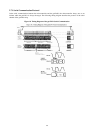
2.9 TCLK Input
The source timing is measured by using the TCLK input as a reference. Also, the reference clock to the on-chip PLLs
are derived from the TCLK. It is therefore crucial to have a jitter-free clock reference.
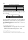
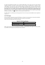
Table 19 shows the requirements for the TCLK signal.
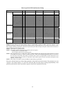
Table 19. TCLK Specification
Frequency 20 MHz to 50 MHz
Jitter 250 ps maximum
Rise Time (10% to 90%) 5 ns
Duty Cycle 40-60
There is also an option to use a crystal (instead of an oscillator) for the TCLK input. This option is selected by pulling
down MFB5 and connecting the crystal between XTAL and TCLK.