


D
IR Receiver Window— Allows remote operation using an optional compatible IR hand
control.
E
Config port — Connect a control PC or other USB device to this port using a
mini-B USB cable (not supplied). Use this port to send Simple Instruction Set (SIS)
commands to the SMD101 for device configuration and control.
• For information on connecting a control PC or other USB device to this port, see
the Front Panel Configuration Port section on page 58.
• For information on SIS commands, see Remote Communication and Control on
page 57.
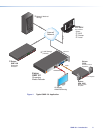
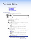
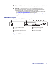
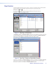
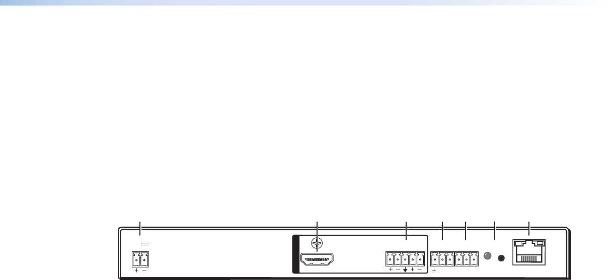
Rear Panel Features
The rear panel of the SMD101 is shown in figure 3 below.
12V
1.0A MAX
POWER
HDMI
LR
AUDIO
Tx Rx G
SG
RS-232
RESET
IR IN
LAN
OUTPUTS
GGA
AB
BCCDDEEFF
A
12 VDC Power connector
E
RS-232 connector (optional)
B
HDMI output connector
F
Reset button and LED
C
Analog audio output connector
G
RJ-45 LAN connector
D
IR input connector
Figure 3. SMD101 Rear Panel
SMD101 • Panels and Cabling 9