


A
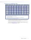
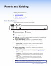
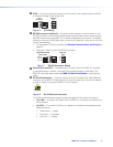
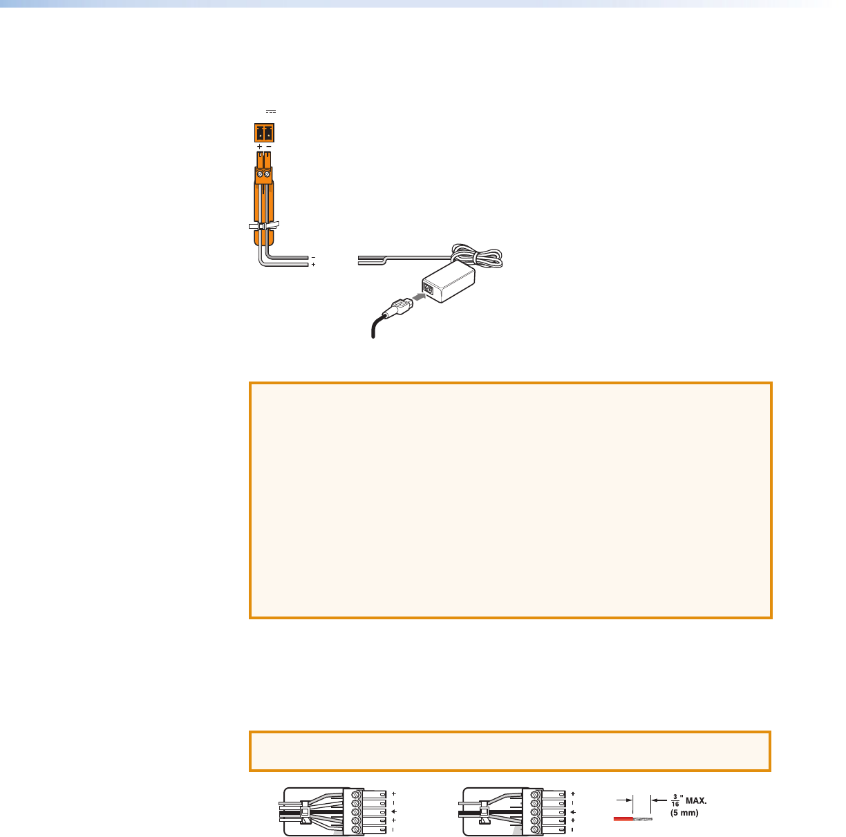
12 VDC power input — Connect the provided 12VDC power supply to the rear panel
captive screw connectors. When power is connected, the front panel power indicator
lights green (see figure 2,
A
on page 8).
AC Power Cord
Ground
+12 VDC
External
Power Suppl
y
(12 VDC, 1 A
)
POWER
12V
1.0A MAX
Rear Panel
Power Receptacle
Figure 4. Power Supply Connection
ATTENTION:
• Always use a power supply provided by or specified by Extron. Use of an
unauthorized power supply voids all regulatory compliance certification and
may cause damage to the supply and the end product.
• Unless otherwise stated, the AC/DC adapters are not suitable for use in air
handling spaces or in wall cavities. The power supply is to be located within the
same vicinity as the Extron AV processing equipment in an ordinary location,
Pollution Degree 2, secured to the equipment rack within the dedicated closet,
podium, or desk.
• The installation must always be in accordance with the applicable provisions of
National Electrical Code ANSI/NFPA 70, article 725 and the Canadian Electrical
Code part 1, section 16. The power supply shall not be permanently fixed to
building structure or similar structure.
B
HDMI output connector — One female HDMI to connect a display or other HDMI
output device.
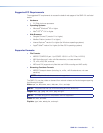
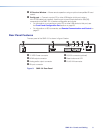
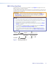
C
Audio output connector — Connect audio output devices using cables with balanced
or unbalanced 3.5mm, 5-pole captive screw connectors. See figure 5 below to wire the
connectors.
ATTENTION: For unbalanced audio, connect the sleeves to the ground contact.
DO NOT connect the sleeves to the negative (–) contacts.
Balanced Audio Output
Tip
Ring
Tip
Ring
LR
Slee
ves
Unbalanced Audio Output
Tip
Tip
LR
Sleeves
Do not tin the wires!
Figure 5. Audio Output Captive Screw Connector Wiring
SMD101 • Panels and Cabling 10