


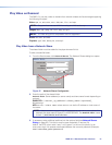


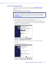

4. Select Install the software automatically (Recommended).
NOTE: You do not need to insert an installation disc.
5. Click Next.
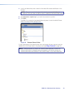
The PC locates the driver and installs it.
6. When the Completed dialog opens, click Finish to close the wizard.
NOTE: The wizard opens only on the first occasion you connect the SMD101 to a
USB port. The wizard reopens only if you connect the SMD101 to a different USB
port or if you connect a different piece of equipment, requiring a different driver, to
the same USB port.
7. Configure the SMD101 as required.
NOTE: There are three SIS commands you may find useful at this point:
• E CI
]
returns the current IP address.
• E 1DH
]
enables DHCP mode.
• E 2BOOT
]
restarts the network inteface to apply changes.
Use DataViewer (see DataViewer on page93) to send the commands and view the
results.
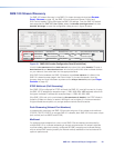
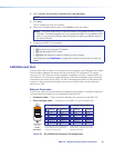
LAN (Ethernet) Port
The rear panel LAN connector on the device can be connected to an Ethernet LAN or WAN.
Communication between the device and the controlling PC is via Telnet (a TCP socket
using port 23). The Telnet port can be changed, if necessary, via SIS or using the SMD101
user interface. This connection makes SIS control of the device possible using a computer
connected to the same LAN or WAN. The SIS commands and behavior of the product are
common to the commands and behavior the product exhibits when communicating by
serial port or USB.
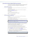
Ethernet Connection
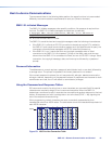
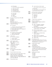
The Ethernet cable can be terminated as a straight-through cable or a crossover cable and
must be properly terminated for your application (see figure 52).
• Crossover cable — Direct connection between the computer and the SMD101.
• Patch (straight) cable — Connection of the SMD101 to an Ethernet LAN.
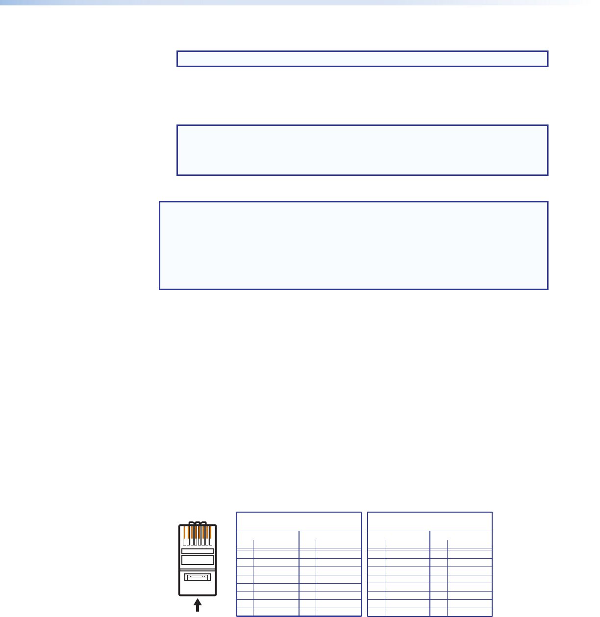
12345678
RJ-45
Connector
Insert Twisted
Pair Wires
Pins:
A cable that is wired as TIA/EIA T568A at one
end and T568B at the other (Tx and Rx pairs
reversed) is a "crossover" cable.
A cable wired the same at both ends is called
a "straight-through" cable because no pin/pair
assignments are swapped.
T568A T568B T568B T568B
Straight-through Cable
(for connection to a switch, hub, or router)
End 1 End 2
Pin Wire Color Pin Wire Color
1 white-orange 1 white-orange
2 orange 2 orange
3 white-green 3 white-green
4 blue 4 blue
5 white-blue 5 white-blue
6 green 6 green
7 white-brown 7 white-brown
8 brown 8 brown
Crossover Cable
(for direct connection to a PC)
End 1 End 2
Pin Wire Color Pin Wire Color
1 white-orange 1 white-green
2 orange 2 green
3 white-green 3 white-orange
4 blue 4 blue
5 white-blue 5 white-blue
6 green 6 orange
7 white-brown 7 white-brown
8 brown 8 brown
Figure 52. RJ-45 Ethernet Connector Pin Assignments
59SMD101 • Remote Communication and Control