


CHAPTER 3 NDA-24219
Page 108
Revision 2.0
NAP-200-008
Sheet 4/10
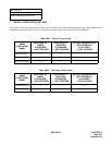
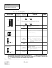
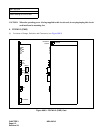
Switch Setting of Circuit Card
The figure in the SWITCH NAME column and the position in in the SETTING POSITION col-
umn indicate the standard setting of the switch. When the switch is not set as shown by the figure and
, the setting of the switch varies with the system concerned.
Note: Set the groove on the switch knob to the desired switch position.
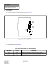
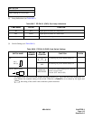
Table 008-4 PN-CP03 (MP) Card Switch Settings (Continued)
SWITCH NAME
SWITCH
NUMBER
SETTING
POSITION
FUNCTION CHECK
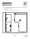
SW2 (Piano Key SW)
2, 3
• When using the PLO card (PN-CK00):
SW2-2
SW2-3
OFF ON
• When not using the internal PLO and the PLO card:
SW2-2
SW2-3
OFF OFF
4
ON
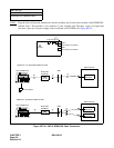
When using RS1 port for built-in
MODEM.
OFF
When using RS1 port for RS-232C.
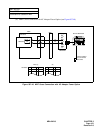
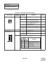
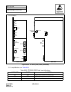
VR (Rotary SW) Variable Resistor for External Hold Tone
Source
(0 - 20 K
Ω
: Clockwise)
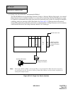
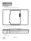
JP0 (Jumper pin) For normal operation
Note: Do not remove this jumper. The
power to RAM will be removed
causing loss of Office Data Pro-
gramming.
DOWN
Not used
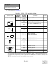
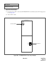
JP1 (Jumper pin) For normal operation
Note: Do not relocate this jumper when
power is turned on.
DOWN
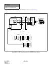
For using External Tone Source
ON
OFF
4
3
2
1
20
0
Front
UP
Front
UP