


CHAPTER 2 NDA-24219
Page 10
Revision 2.0
3.3 Functional Outline of Circuit Cards
3.3.1 Control Circuit Card
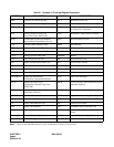
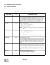
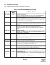
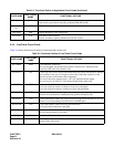
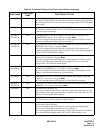
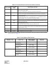
Table 2-4 shows the functional outline of each control circuit cards.
Table 2-4 Functional Outline of Control Circuit Cards
CARD NAME
FUNCTIONAL
NAME
FUNCTIONAL OUTLINE
PN-CP03 MP Main Processor Card
This card is equipped with Memory, TDSW (1024CH
×
1024CH), 16-Line
CFT, DTMF Sender, Clock, PLO (receiver mode 2 ports), RS-232C Ports (2
ports) for MAT/Built-in SMDR, modem for remote maintenance, and
Music-On-Hold tone source (Melody IC/TNT), 4-circuit PBR (for PB
calling or DID). This card is used on the basis of one per system.
PZ-PW86 PWR Main Power Supply Card
Input: AC 120 V (50 Hz/60 Hz)
Output: –27 V (4.5 A), +5 V (7.5 A)
One card is mounted in PIM.
Note: This card does not provide ring generator or message wait volt-
age.
PZ-PW112 PWR Main Power Supply Card
Input: AC 120 V (50 Hz/60 Hz)
Output: –27 V (3.5 A), +5 V (4.0 A)
One card is mounted in PIM.
Note: This card does not provide ring generator or message wait volt-
age.
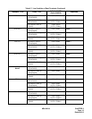
PN-BS00-B BS00 Bus Interface Card for PIM0
This card is equipped with functions of driver/receiver of various signals,
functions of adjusting gate delay timing and cable delay timing, functions
of monitoring I/O Bus and PCM Bus, and functions of controlling power
supply. When the system consists of two PIMs, this card is mounted one in
PIM0
PN-BS01-B BS01 Bus Interface Card for PIM1
This card is equipped with functions of driver/receiver of various signals,
functions of adjusting gate delay timing and cable delay timing, functions
of monitoring I/O Bus and PCM Bus, and functions of controlling power
supply. When the system consists of two PIMs, this card is mounted one in
PIM1.
SPN-DAIB DAIB Firmware Processor-Bus Card—With T1
Used when installing PIM as a Remote PIM
SPN-DAIC DAIC Firmware Processor-Bus Card—With T1
Used when installing PIM as a remote PIM expanded to 43 ports.