


NDA-24219 CHAPTER 2
Page 17
Revision 2.0
4. CIRCUIT CARD INSTALLATION CONDITIONS
4.1 Circuit Card Mounting Slots
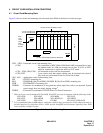
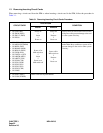
Figure 2-6 shows circuit card mounting slots allocated in the PIM, on the basis of circuit card type.
Figure 2-6 Circuit Card Mounting Slots
LT01 - LT08 : Line/trunk circuit card mounting slots
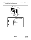
• LT00 : No connection to MDF. When NEAXmail AD8 is mounted here, inter-
nal modem leads for AD8 are brought out on pins 25 & 50 of LTC1
cable for connection to single-line station or C.O. trunk.
• LT01 - LT04, LT06, LT08 : All line/trunk circuit cards can be mounted.
• LT05, LT07 : 4-port circuit cards that require cabling may be mounted only when 8-
port cards are not mounted in the slot to the left of them.
AP0 - AP5 : Application circuit card mounting slots
MP : PN-CP03 mounting slot
BUS : PN-BS00-B (Slot 08 on PIM0), PN-BS01-B (Slot 09 on PIM1) mounting slot
PWR : PZ-PW86/PW112 mounting slot
PWR0B : Connector for termination of ring generator when single-line card(s) are mounted. System
power supply does not supply ringing voltage
2
PWR0C : Connector for termination of PW91 Power for Zone Transceivers
1
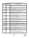
When an 8-port card is mounted in Slot 04/06, Slot 05/07 can only be mounted with the following cards:
SPN-AP00 SPN-AP01 SPN-ME00 SPN-SC01
SPN-SC02 SPN-4RSTB SPN-4RSTB-911 SPN-4RSTC
SPN-CK00 SPN-CC00 PN-M03 SPN-SC03 (CSH)/(ICH)
2
It is recommended that an APR adapter, which has a built-in ring generator, be used in dual-port mode to
provide interface for single-line devices. APRs provide hookflash and disconnect signaling when 1800
series software or higher is used.
00
LT
01
LT
02
LT
03
LT
04
LT
/
AP0
05
LT
/
AP1
06
LT
/
AP2
07
LT
/
AP3
08
LT
/
AP4
09
MP
/
BUS
PWR0C
vacant
space
P
W
R
LTC1
LTC0
PWR0B
(10 min. Internal Battery Back-Up Standard)
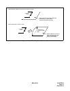
4-Port Card Mounted
8-Port Card Mounted
AD-8
uses
vacant
space
when
mounted
Slot 00
444444444
888880
1
80
1
8
Number of Ports Available per Slot