


12
13
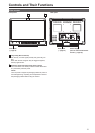
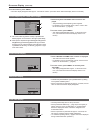
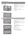
Controls and Their Functions (continued)
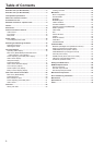
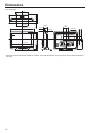
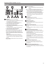
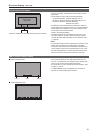
Rear panel
DVI-I
SDI VIDEO
RS-485 GPI
RS-232C
AUDIO
1
IN
OUT
IN
R L
OUT IN
IN
OUT
(3G)
2
2 6 81 5
3 4 7
1
2
3
4
1
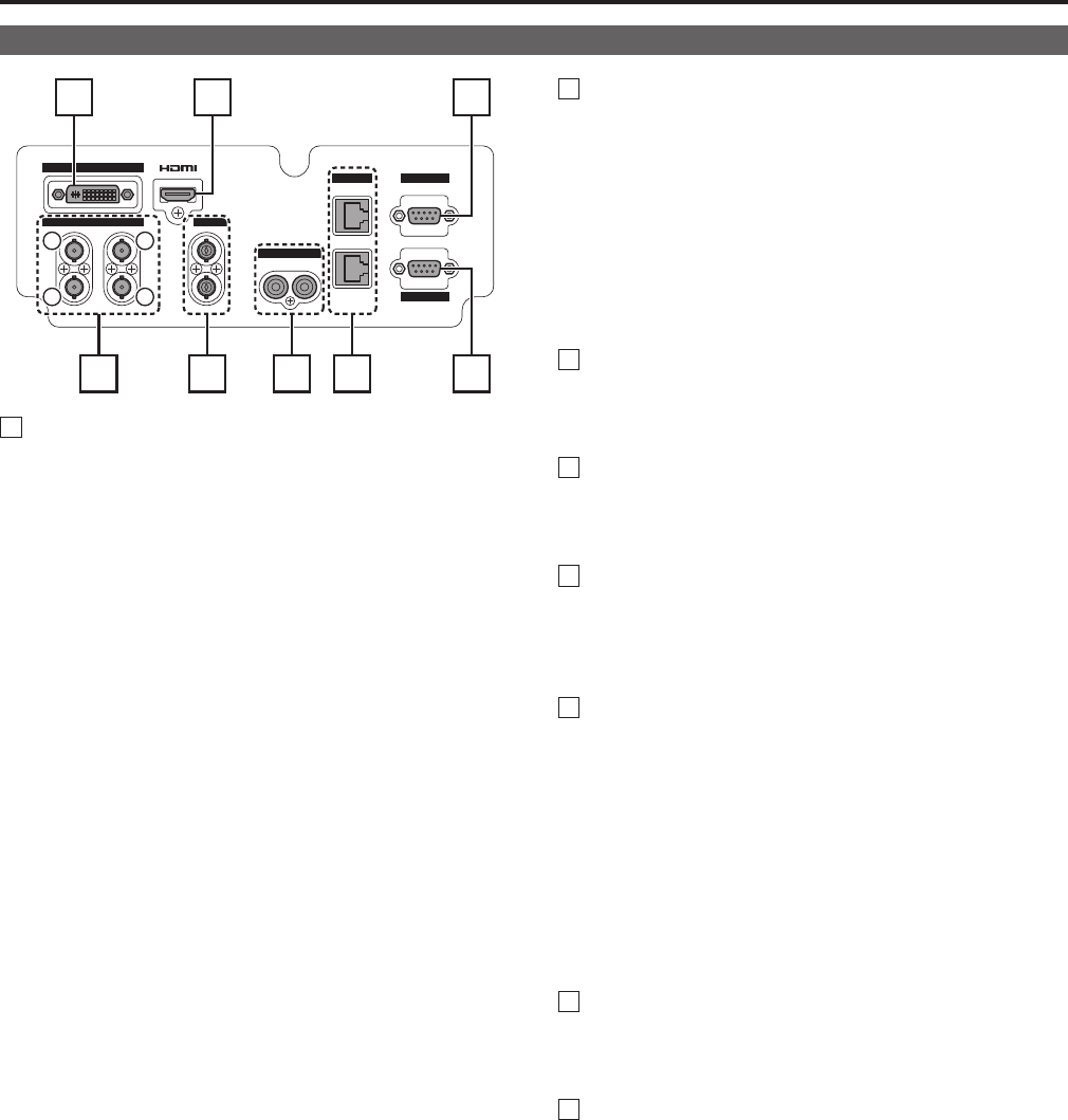
SDI terminal
A SDI1 (3G/HD/SD) input terminal (BNC)
This is the SDI input terminal. (Compatible with 3G-SDI
and 3G/HD/SD automatic switching)
In 3D assist mode, input images for the left eye (L).
B SDI1 active through output terminal (BNC)
This terminal outputs SDI1 input as is.
C SDI2 (HD/SD) input terminal (BNC)
This is the SDI input terminal. (Compatible with HD/SD
automatic switching)
In 3D assist mode, input images for the right eye (R).
D SDI2 active through output terminal (BNC)
This terminal outputs SDI2 input as is.
• When this output is used to daisy-chain
*
1
multiple moni-
tors, the quality of the original signal, cable length, the
number of connected devices and other factors all come
into play to deteriorate picture quality and introduce noise.
*
1
Daisy-chain:
Refers to connecting the through-out signal from a
device to the input of a second, third or more devices
in a linear series, thus using a single signal in multiple
devices.
• Use a 5C-FB or equivalent cable to make connections to
an SDI terminal.
2
VIDEO terminal (BNC)
*
2
*
3
IN : This is the VIDEO signal (composite signal) input
terminal.
OUT : This is the input signal through-out terminal.
*
2
Unless a cable is connected to the VIDEO OUT terminal,
the VIDEO IN terminal is automatically terminated at
75 Ω. Connecting a cable releases this termination.
*
3
Since a connection to the through-out terminal releases the
75 Ω termination of the unit, the level of the VIDEO signal
input to the unit may become too large depending on the
connected device.
3
DVI-I terminal
This is the DVI-signal input terminal.
• Use double shielded cable for making connections to a
DVI-I terminal.
4
HDMI terminal (Type A)
This is the HDMI input terminal.
• Use double-shielded cable for making connections to an
HDMI terminal.
5
AUDIO input terminal (pin jack)
This is the common audio input terminal for all video input
terminals.
• Use shielded cable for making connections to an AUDIO
input terminal.
6
RS-485 input/output terminal (RJ-45)
External control is possible by using an RS-485 signal.
• Use shielded cable for making connections to an RS-485
input/output terminal.
• Make sure that the cable is fully inserted in the terminal
and cannot easily be pulled out.
• A loop-through connection using the RS-485 input and
output terminals allows operation of multiple monitors (up
to 32 monitors).
• Connect a terminator (120 Ω) between the first and sec-
ond pin of the RS-485 OUT terminal on the last monitor in
the chain.
7
GPI input terminal (D-SUB, 9 pins)
External control is possible by using a GPI signal.
• Use shielded cable for making connections to the GPI
input terminal.
8
RS-232C input terminal (D-SUB, 9 pins)
External control is possible by using an RS-232C signal
• Use shielded cable for making connections to an RS-232C
input terminal.