


35
DSR Series
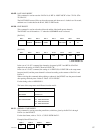
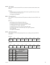
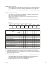
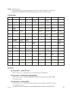
Request DATA-1
01 02 03 04 08 10 20 30 11
**
**
*3
22
**
**
*3
33
**
**
*3
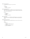
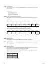
Response
74.00 : TIMER-1 DATA O
74.01 : TIMER-2 DATA O
74.04 : LTC TIME DATA OO
78.04 : LTC TIME & UB DATA OO
74.05 : LTC U-BIT DATA OO
74.06 : VITC TIME DATA O
*1
O
*2
78.06 : VITC TIME & UB DATA O
*1
O
*2
74.07 : VITC U-BIT DATA O
*1
O
*2
74.14 : LTC INTERPOLATED TIME DATA OO
78.14 : LTC INTERPOLATED TIME & UB DATA OO
74.16 : VITC HOLD TIME DATA O
*1
O
*2
78.16 : VITC HOLD TIME & UB DATA O
*1
O
*2
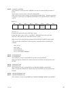
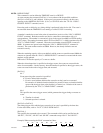
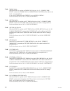
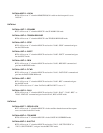
BIT-7 BIT-6 BIT-5 BIT-4 BIT-3 BIT-2 BIT-1 BIT-0
VITC UB LTC UB TIMER-1TIMER-2 VITC TIME LTC TIME
MSB LSB
78.08 : GEN TC & UB DATA
When the DEVICE receives the “61
..
..
.0A : TC GEN DATA SENSE” command, if the DATA-1 is
“11”, the TIME DATA will be added to the DATA-1 through DATA-4 of the “74
..
..
.08 : GEN
TIME DATA” command and the user bit data will be added to the DATA-5 to DATA-8.
For the data format, refer to “24
..
..
.31 : CUE UP WITH DATA” and “4X
..
..
.05 : USER’S BIT PRESET”.
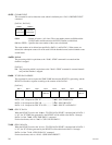
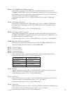
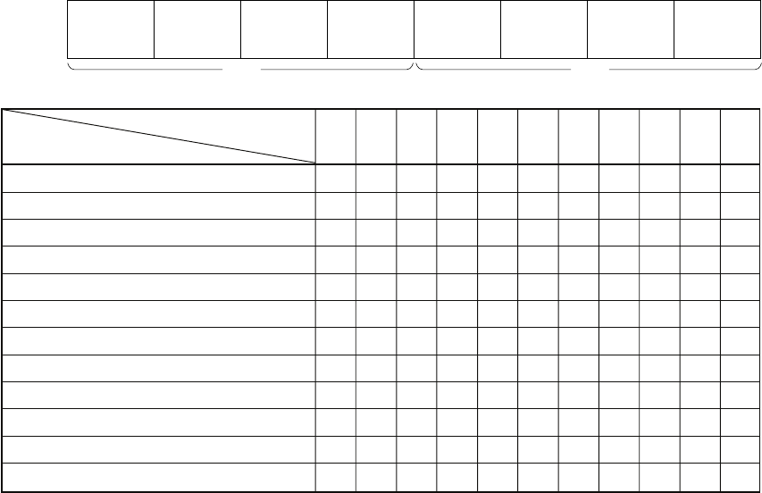
61.0C : CURRENT TIME SENSE
This command is used for requesting the TIME DATA or USER BIT, and the DEVICE will
make a response according to the contents of DATA-1.
When the accurate TIME DATA is requested in the normal playback mode, the following
condition must be satisfied.
. Select external reference mode.
. CURRENT TIME SENSE command and its return must be completed within the field-2.
[DATA-1]
The response command according to the request command is as follows.
Note :
*1 : The DSR-60/60P/70/70P/80/80P/85/85P returns the “70.0D: REQUEST TIME DATA MISSING because the VITC READER is not
built.
*2 : The DSR-60/60P/70/70P/80/80P/85/85P does not return the VITC DATA because the READER is not built. (LTC DATA only)
*3 : When the request command is “DATA-1 = 11, 22, 33, the TIME DATA is returned with DATA-1 through DATA-4 and the USER BIT
DATA is returned with DATA-5 through DATA-8.
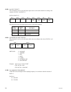
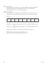
74.00 : TIMER-1 DATA
When the DEVICE is required the TIMER-1 data by the “61.0C : CURRENT TIME SENSE”
command, the TIMER-1 data (COUNTER) will be added to the DATA-1 through DATA-4.
At that time, the DF/NDF mode of TIMER-1 is set to the BIT-6 of DATA-1.
For the data format, refer to “24.31 : CUE UP WITH DATA”.