2
DSR Series
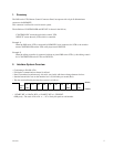
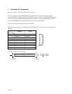
MSD LSD
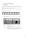
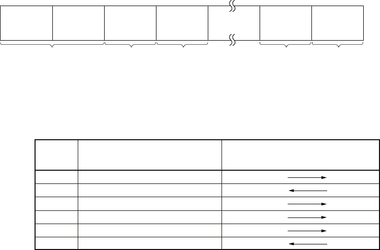
1 BYTE 1 BYTE 1 BYTE 1 BYTE 1 BYTE
CMD-1 CMD-2 DATA-1 CHECKSUM
DATA
COUNT
DATA-n
(MAX.15)
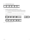
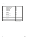
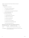
CMD-1 Function
Direction
Controller Device
0 SYSTEM CONTROL
1 SYSTEM CONTROL RETURN
2 TRANSPORT CONTROL
4 PRESET & SELECT CONTROL
6 SENSE REQUEST
7 SENSE RETURN
3. Command Block Format (CMD Block)
3-1. VTP Command
The communication between the CONTROLLER and the DEVICE is composed of CMD-1 + DATA
COUNT, CMD-2 + DATA and CHECKSUM, and is transmitted from CMD-1 + DATA COUNT in
order.
When the DATA COUNT is zero, the DATA is not transmitted.
When it is not zero, the DATA corresponded with the value is inserted between CMD-2 and CHECK-
SUM.
The command block can be illustrated as shown.
CMD-1 : CMD-1 classifies the command into the main groups which indicates the function and direction
of the data words to follow.
Contents of CMD-1
DATA COUNT : DATA COUNT indicates the number of data bytes that are added to the
command. (0 to FH)
CMD-2 : Specifies the respective commands.
DATA : The number of data bytes and their contents are defined by the respective
commands.
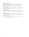
CHECKSUM : The CHECKSUM is the lower eight value of the sum of the data bytes from
the first byte to the last byte immediately before CHECKSUM. It is used to
check the errors that are incurred by the data communication.


