


13
21
18
20
19
1
22
23
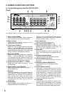
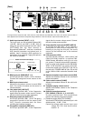
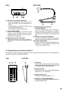
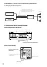
[Rear] [Right Side]
18. DC power input jack [DC POWER IN]
• A jack with non-polarity. Connect the 24-V DC
power (AC adapter). (See the specifications on
p. 69.)
• The VM amplifier can supply the power to only
a single Remote Microphone.
(Line resistance: within 24 Ω/one way)
19. Link connector [LINK]
A female RJ45 connector. Connects the VM
amplifier or other RM-200M units (up to 4 units
connectable per system) using the cable of
Category 5 STP straight type.
20. Microphone volume control [MIC]
Adjusts the volume of the unit's gooseneck
microphone or the external microphone input
(No. 21).
21. External microphone input jack
[EXTERNAL MIC IN]
A 3.5 mm-diameter Mini-jack. Connects a
electronic condenser microphone (ex. headset).
Inserting a Mini-plug switches the microphone
sound source to that which is connected to this
jack.
22. Extension connector [EXTENSION]
Connects the RM-210 Remote Microphone
Extension using the cable supplied to the RM-210.
23.Function setting switch
Used for setting the Remote Microphone's Unit
numbers (1 – 4) and functions as shown in the
"Function Setting table" below.
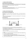
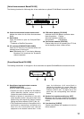
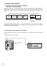
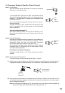
6.3. Remote Microphone Extension RM-210
The RM-210 is used to select the optional EV-200 Voice Announcement Board's voice message when
connecting 2 VM-2120 or VM-2240 amplifiers.
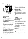
[Top] [Left Side]
1
3
2
4
1. Name label
Insert the label (not thicker than 0.2 mm) indicating
the name of each panel control and indicator. (See
p. 60 "NAME LABEL PREPARATION.")
2. Message indicator
Lights green when the corresponding Message
Selector Key (1 – 5) is pressed.
3. Message selector key
Selects the broadcast message (1 – 5).
4. Extension connector [EXTENSION]
Connects to the RM-200M Remote Microphone
using the supplied cable.