


40
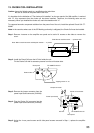
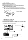
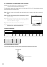
17. RACK MOUNTING
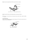
Step 1. Remove 4 plastic feet from the unit's bottom side.
Step 2. Remove 2 screws on each side (located near the front).
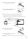
Step 3. Fix the Rack Mounting Bracket MB-36 to the unit with its accessory screws and plain washers.
Note: Do not use the removed screws in the above step.
Step 4. Mount the unit on an equipment rack using the Bracket's accessory screws and fiber washers.
Note: When mounting the unit in an equipment rack not made by TOA, prepare separately the screws
and washers appropriate for the rack.
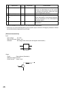
18. AMPLIFIER INPUT CONNECTION
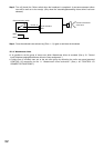
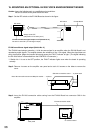
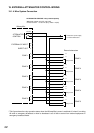
18.1. Two Amplifiers Stack-Connection
When 2 VM amplifiers are stack-connected, connect the master unit's "PRE OUT" to the sub-unit's "POWER
AMP IN" as well as the LINK-to-LINK connection between both units.
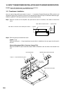
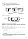
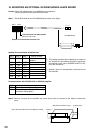
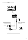
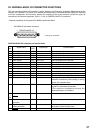
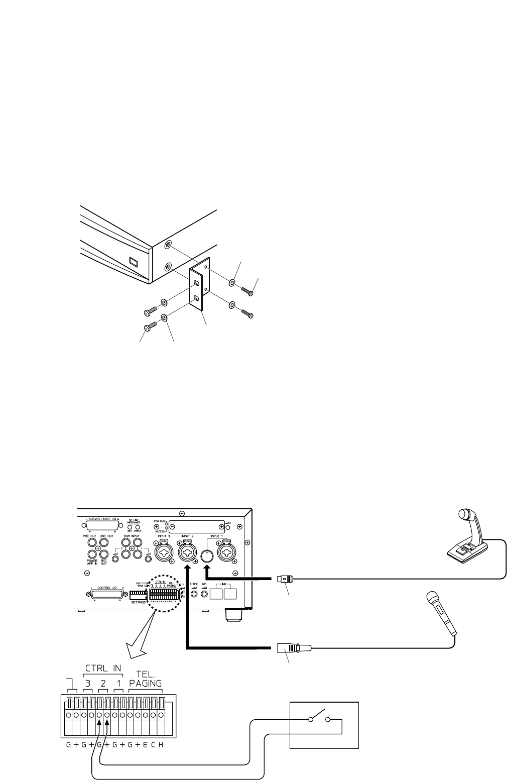
18.2. Microphone Connection to the VM Amplifier
Note: The screws and washers as illustrated are
all supplied with the MB-36.
Plain washer
Rack Mounting Bracket MB-36 (optional)
M4 x 12 screw
Fiber washer
Rack mounting screw
VM amplifier
3
4
* Prepare the switch assembly locally at your end.
XLR type connector
DIN connector
Paging microphone PM-660D
(with short-off press-to-talk switch)
Microphone
Press-to-talk switch box*
(Remote switch)