


14
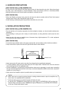
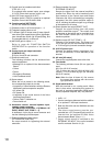
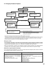
7. SYSTEM CONFIGURATION
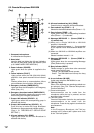
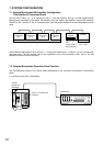
7.1. Remote Microphone/VM Amplifier Configuration
(The Number of Connected Units)
Set the total number (0 – 5) of equipment (up to 1 sub-VM amplifier and up to 4 RM-200M Remote
Microphones) connected to the master VM amplifier using the master VM amplifier's internal DIP switches
SW3-No. 6, No. 7 and No. 8 "No. of connected units." Note that these switches in the sub-VM amplifier are not
used.
Set the Remote Microphone's Unit number (1 – 4) using DIP switches No. 1 and No. 2 on the microphone's
right side panel. The Unit number may be set regardless of the unit's connection order. (See p. 49 "VM
Amplifier's Internal Function Switches.")
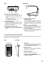
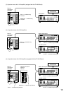
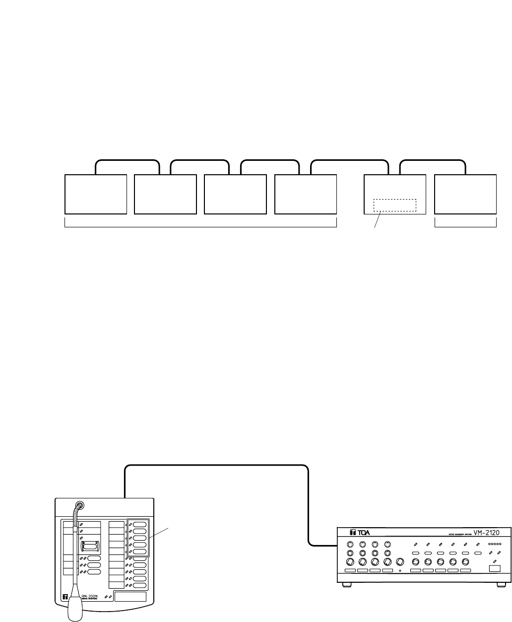
7.2. Remote Microphone Operation Panel Function
The Zone/Message selector key function differs depending on the connected VM amplifier as described
below.
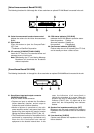
(1) 5 speaker zones with 1 VM amplifier
Remote
microphone
No. 2
Remote
microphone
No. 1
Remote
microphone
No. 3
Remote
microphone
No. 4
Master VM
amplifier
EV-200
Sub-VM
amplifier
Sub-VM amplifier
(0 or 1 unit)
The number of Remote Microphones (0 – 4 units)
Voice
announcement
board (optional)
Remote
microphone
RM-200M
VM amplifier
Zone 1 – 5 selector key
/indicator