


8
12
8
9
1
2
15
16
13 14
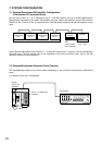
6
7
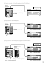
10
11
11
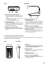
3
4
5
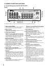
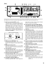
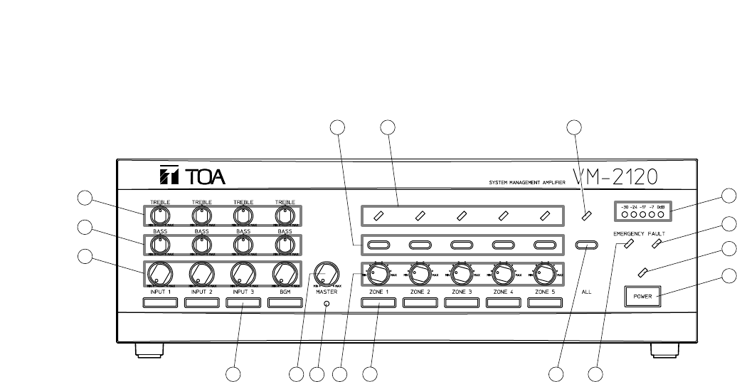
6. NOMENCLATURE AND FUNCTIONS
6.1. System Management Amplifier VM-2120/-2240
[Front]
1. Power switch [POWER]
Turns on and off the power. Press continuously
for 0.3 second or more to turn off the power.
2. Power indicator
Lights when the power is turned on, and is
extinguished when turned off.
3. Treble control [TREBLE]
Adjusts the level of high frequency sound from
Inputs 1 – 3 and the BGM Input. Turn clockwise
to accentuate the high frequency output and
counterclockwise to attenuate it. The center click
position indicates a flat frequency response.
4. Bass control [BASS]
Adjusts the level of low frequency sound from
Inputs 1 – 3 and the BGM Input. Turn clockwise
to accentuate the low frequency output and
counterclockwise to attenuate it. The center click
position indicates a flat frequency response.
5. Input volume control [INPUT 1 – 3, BGM]
Adjusts the sound volume for Inputs 1 – 3 and
the BGM Input.
6. Master volume control [MASTER]
Adjusts the mixed sound volume for Inputs 1 – 3
and the BGM Input.
7. Reset key
Press this recessed key with a pointed object to
reset the unit's internal computer if the unit
malfunctions, key inputs are not accepted or
other troubles occur. Note that other preset
parameters are not reset. This key is also used
in combination with other keys to enter the
setting mode.
8. Zone indicator
Lights to indicate the broadcast zone (Zones 1 –
5) selected with the Zone Selector key.
Flashes to show the speaker zone which is being
inspected or has failed when the surveillance
function operates. (See p. 11 No. 41.)
9. Zone selector key
Selects the desired broadcast zone.
10. Zone volume control [ZONE 1 – 5]
Adjusts the broadcast volume for Zones 1 – 5 in
6 steps: 0 dB (Max. position), –3 dB, –6 dB, –10
dB, –15 dB, and –20 dB (Min. position).
11. Name label
Used for indicating the name of each input and
zone. (The blank labels are supplied with the
unit.)
12. All-zone broadcast indicator
Lights when the All-Zone Broadcast is made.
13. All-zone broadcast key [ALL]
Press this key when making the All-Zone
Broadcast.
14. Emergency indicator [EMERGENCY]
Lights when the unit is in Emergency mode.
(See p. 21.)
15. Failure indicator [FAULT]
Lights when communications with the remote
microphone or expansion amplifier are not
correctly performed, the Voice Announcement
board malfunctions, or speaker line failure (short
circuit, ground fault, or disconnection) occurs.
Failure information is transmitted from the rear
panel-mounted control input and output
connector [CONTROL I/O] (No. 30).
16. Level meter
Indicates the power amplifier's output level,
reaching "0 dB" at rated output (100 V). In general
use, broadcast volume should be set below the
point where the red indicator (0 dB) begins to light.
The VM-2120 is shown in the figure. The VM-2240 is the same in both appearance and function.