


33
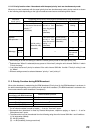
13. CHOKE COIL INSTALLATION
Caution: Leave the following work to a qualified service technician.
Be sure to switch off the power before the work.
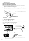
If a checkbox for the indication of "The choke coil is installed." on the rear panel of the VM amplifier is marked
with "X", this represents that the choke coil has been installed. Therefore, the following tasks are not
necessary. When you installed the choke coil, mark the checkbox with "X".
To suppress harmonic component radiation from the power line of the unit, install the optional Chock Coil CT-
200M.
Note: In the countries where use of the CE Marking conformity is obligated, the Choke Coil must be installed.
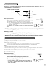
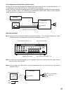
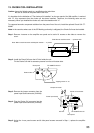
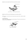
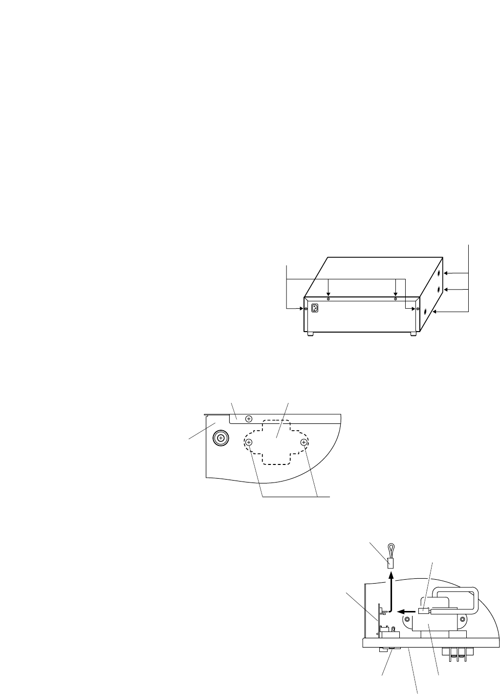
Step 1. Remove 4 screws on the amplifier rear panel and a total of 6 screws on the sides to remove the
cover.
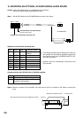
Step 2. Install the Chock Coil near the AC inlet inside the unit.
Fix the Choke Coil with its accessory screws from the unit bottom side.
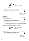
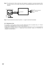
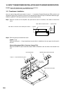
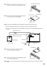
Step 3. Remove the jumper connector from the
power input board connector (CN1202).
Step 4. Plug the Choke Coil connector into the
power input board connector (CN1202).
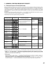
Step 5. Using the 4 rear panel screws and 6 side panel screws removed in Step 1, replace the amplifier
cover.
Side: M4 x 8 machine screw ..... 3 pieces each
Rear: M3 x 6 machine screw and M3 plain washer ..... 4 pieces
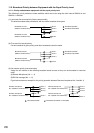
Rear panel
Bottom side
CT-200M Choke coil
Tapping screw 4 x 10
Jumper connector
Choke coil connector
Power input board
AC inlet
Rear panel
CT-200M Choke coil
3
4