


34
14. INPUT TRANSFORMER INSTALLATION AND ITS BOARD MODIFICATION
Caution: Leave the following work to a qualified service technician.
Be sure to switch off the power before the work.
14.1. Transformer Installation
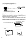
You can convert the audio input section in Input 1 – 3 terminals, Remote Microphone (RM) terminal, and
Telephone Paging (TEL) terminal on the unit from electronically-balanced input to transformer-balanced type.
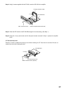
Solder the optional IT-450 input transformer to the required input section.
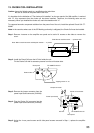
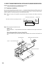
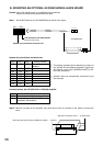
Step 1. Remove 4 screws on the amplifier rear panel and a total of 6 screws on the sides to remove the
cover.
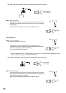
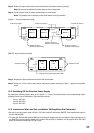
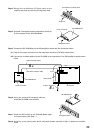
Step 2. Removing the input transformer board
[Inputs 1 – 3]
Remove the Inputs 1 – 3 input transformer board, which is installed on the rear upper circuit board in
the unit.
[Remote Microphone (RM) or Telephone Paging (TEL)]
Remove the RM/TEL input transformer board, which is installed on the rear lower circuit board in the
unit.
Side: M4 x 8 machine screw ..... 3 pieces each
Rear: M3 x 6 machine screw and M3 plain washer ..... 4 pieces
Inputs 1 – 3 input transformer board
Rear upper
circuit board
Rear lower circuit board
RM/TEL input transformer board
Input transformer