


9
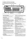
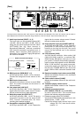
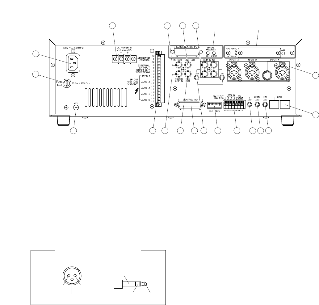
[Rear]
17. Audio input terminal [INPUT 1, 2, 3]
The input level can be switched between MIC
(–60 dB*
1
, 600 Ω) and LINE (–10 dB*
1
, 600 Ω)
using the rear panel-mounted function switch
[SETTINGS] (No. 29). Each terminal is
electronically balanced*
2
, and has a combined
XLR (female) connector and phone jack. In
addition, Input 1 features a DIN connector for
connection of an optional Paging Microphone
VR-1001B or PM-660D.
18. BGM input jack [BGM INPUT 1, 2]
An RCA pin jack with –20 dB*
1
, 10 kΩ, monaural.
Connect the background music source to this
jack.
19. BGM input volume control
Adjusts the broadcast volume for each BGM
input. The volume increases as the control is
turned clockwise.
20. Line output jack [LINE OUT]
An RCA pin jack with 0 dB*
1
, 10 kΩ. Outputs the
signal before the master volume control. Connect
this jack to the line input of other equipment.
21. Recording output jack [REC OUT]
An RCA pin jack with 0 dB*
1
, 10 kΩ. This jack is
connected in parallel to the line output [LINE
OUT]. Connect a cassette deck, etc. when
recording the broadcast contents.
22. Preamplifier output jack [PRE OUT]
An RCA pin jack with 0 dB*
1
, 10 kΩ. Outputs the
signal after the master volume control. Connect
this jack to other power amplifier.
23. Power amplifier input jack [POWER AMP IN]
An RCA pin jack with 0 dB*
1
, 10 kΩ. Connect a
preamplifier or other external equipment. By
inserting a pin plug into this jack, the sound
source can be switched over to the external
equipment.
24. Link connector [LINK]
An RJ45 female connector. Links another VM
(VM-2120/-2240) amplifier*
3
or optional RM-
200M Remote Microphone units (up to 4 units
per system). Features electronically balanced*
2
input to accept audio signals from the RM-200M.
When 2 VM amplifiers are stack-connected,
connect the master unit's "PRE OUT" (No. 22) to
the sub-unit's "POWER AMP IN" (No. 23) as well
as the LINK-to-LINK connection between both
units.
25. Remote microphone input volume control [RM]
Adjusts the broadcast volume for the connected
remote microphone.
26. Chime volume control [CHIME]
Adjusts the broadcast volume for the unit's built-
in chime.
27. Telephone paging volume control
Adjusts the broadcast volume for the Telephone
Paging Input.
28. External connection terminal
[TEL PAGING, CTRL IN 1, 2, 3, 24 V OUT]
A push-in terminal block. This terminal block
features the following connection sections.
(1) Telephone paging input [TEL PAGING]
Voice sound: Electronically-balanced input*
2
with
shield terminal, –10 dB*
1
, 10 kΩ.
Control: No-voltage make contact input, open
voltage: 30 V DC, short-circuit current:
under 0.1 A
EV-200
SV-200M
33
34
32 20
22
18
24
35
31
2123
25
2627
28
29
30
19
17
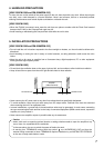
Usable connectors and plugs
• XLR type male connector
• Phone plug
Pin 1: Ground
Sleeve: Ground
Pin 2: Hot
Tip: Hot
Pin 3: Cold
Ring: Cold
The figure above shows the 230 V AC versions of the VM-2120 and VM-2240. The 120 V AC versions are the same in
both appearance and function except the rating indications of the AC inlet (No. 33) and fuse holder (No. 34).