


43
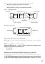
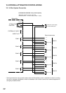
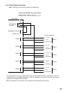
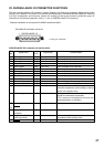
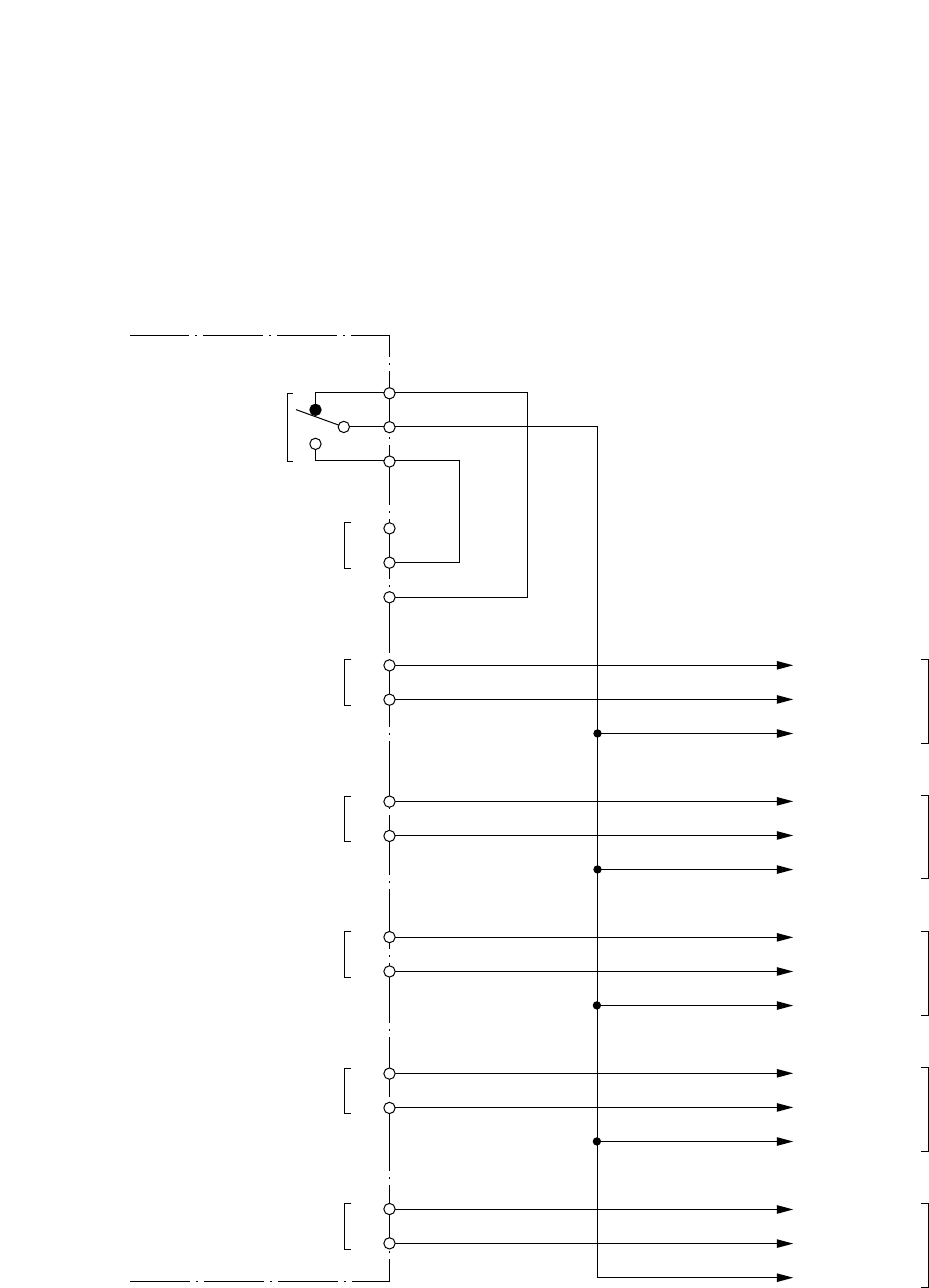
19.2. 3-Wire System Connection
Note: 3-wire system cannot be used with the SV-200M board.
*
1
This figure shows the relay operation status when the VM amplifier's power is switched off, when it is
making All-zone or emergency broadcast or when its broadcast is cut off due to control from external
equipment in emergency broadcast mode.
*
2
May be connected to any C terminal. (This C terminal is located closest to N1 terminal.)
ATTENUATOR CONTROL relay contact capacity
Withstand voltage: 30 V DC, 125 V AC
Contact current: Under 7 A (DC), under 7 A (AC)
ATTENUATOR
CONTROL*
1
EXTERNAL SP INPUT
DIRECT OUT
ZONE 1
ZONE 2
ZONE 3
ZONE 4
ZONE 5
N1 (NC)
N2 (NO)
H
*
2
C
C
H
H
C
H
C
H
C
H
C
H
C
H (100 V)
C (0 V)
EMERGENCY
ZONE 1
H (100 V)
C (0 V)
EMERGENCY
ZONE 2
H (100 V)
C (0 V)
EMERGENCY
ZONE 3
H (100 V)
C (0 V)
EMERGENCY
ZONE 4
H (100 V)
C (0 V)
EMERGENCY
ZONE 5
VM amplifier
External attenuators