


35
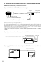
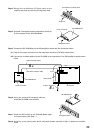
Step 3. Solder the input transformer to the removed input transformer board (5 places).
Note: Be sure not to mistake the solder side for the mounting side.
Step 4. Cut off jumper wires (2 places marked with X for each input).
Note: The jumpers are on the back of the circuit board in the figure below.
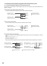
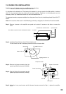
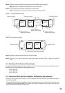
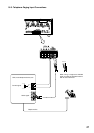
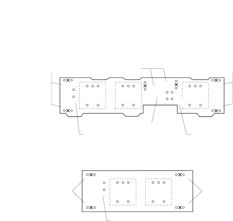
[Inputs 1 – 3 input transformer board]
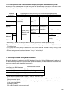
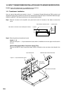
[RM/TEL input transformer board]
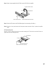
Step 5. Replace the input transformer board on the circuit board.
Step 6. Using the 4 rear panel screws and 6 side panel screws removed in Step 1, replace the amplifier
cover.
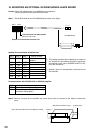
14.2. Switching Off the Phantom Power Supply
By cutting the following jumper wires on the Inputs 1 – 3 Input Transformer Board, the corresponding input's
phantom power can be switched off. (See the figure above.)
Input 1: SJP1301
Input 2: SJP1304
Input 3: SJP1307
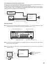
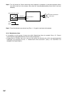
14.3. Instructions When the Sub- and Master VM Amplifiers Are Connected
• Be sure to cut the jumper wires SJP1401, SJP1402, and SJP1403 on the RM/TEL input transformer board in
the sub-VM amplifier.
• To make the Remote Microphone (RM) input transformer-isolated, be sure to install the input transformer on
the RM/TEL input transformer board in the master VM amplifier. In addition, cut the jumper wires SJP1402
and SJP1403 while remaining SJP1401 intact.
INPUT 1 INPUT 2 INPUT 3
(SJP1303)
(SJP1301)
(SJP1302)
(SJP1306)
(SJP1305)
(SJP1304)
(SJP1307)
(SJP1308)
(SJP1309)
Jumpers for Input 1
Jumpers for Input 2
Jumper for Input 1
phantom power supply
Jumper for Input 3
phantom power supply
Jumper for Input 2
phantom power supply
Jumpers for Input 3
RM TEL
(SJP1402)
(SJP1401)
(SJP1403)
(SJP1404)
(SJP1405)
Jumpers for RM
Jumper for DC power supply to the RM
Jumpers for TEL