


49
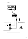
23.2. VM Amplifier's Internal Function Switches
Caution: Leave the following work to a qualified service technician.
Be sure to switch off the power before the work.
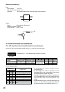
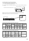
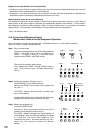
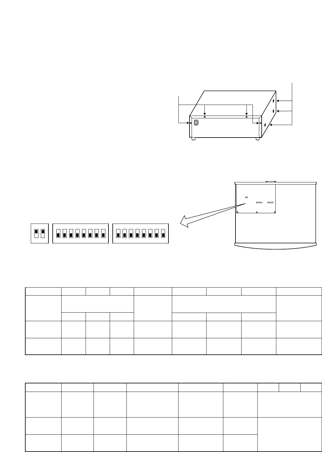
Step 1. Remove 4 screws on the amplifier rear panel and a total of 6 screws on the sides to remove the
cover.
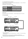
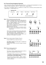
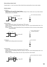
Step 2. Set the amplifier's internal DIP switches SW2, SW3, and SW4 according to the table below.
Step 3. Replace the amplifier cover using the screws removed in Step 1.
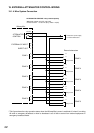
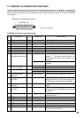
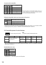
SW2 switch setting (All switches are factory-preset to OFF position.)
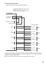
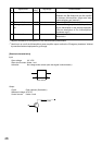
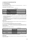
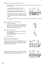
SW3 switch setting (All switches are factory-preset to OFF position.)
* This function is set in relation to the SW2-8 switch. (See p. 27 "GENERAL-PURPOSE BROADCAST
PRIORITY" for details.)
Side: M4 x 8 machine screw ..... 3 pieces each
Rear: M3 x 6 machine screw and M3 plain washer ..... 4 pieces
ON
1
2
ON
1
2345678
ON
1
2345678
SW4 SW3
SW3
SW4
SW2
SW2
VM amplifier's front panel
Internal DIP switches
Switch No. 1 2 3 4 5 6 7 8
Function
Input 1 Input 2 Input 3 Message 3 Message 4 Message 5
ON 1 1 1 1 3 3 3
OFF 2 2 2 2 1 1 1
Priority Mode
for Same
Priority Unit
Unit No. Priority
(Numerical order)
First/Last
Priority
Inputs 1 – 3
Broadcast Priority Level
Voice Announcement Board's
Message Priority Level
TEL Paging
Priority Level
Switch No. 1 2 3 4 5 6 7 8
Function
ON Mixed Silent On Sub-unit
(off)
OFF Off
(on)
First/Last
Priority*
First-come
first-served
Last-come
first-served
Not mixed
Evacuation
message
Master
unit
Priority 2
Mixing
Mode after
Emergency Talk
Input 3/LINE
(Input 3/MIC)
Chime On/Off
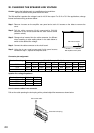
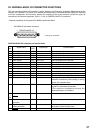
Unit Type No. of Connected
Units
See the Connected
unit No. table on the
next page.