


15
BEGIN INSTALLATION
1. Preparation
Follow these steps carefully:
A. Review the design of the demonstration area.
• Make sure the display fixture is correct for your installation.
• Look at the supplied system wiring diagram, or choose one from this manual to serve as an
example. Examples are in Appendix A: Sample Systems.
• Gather the owner’s manuals of other products that are part of your system for reference during
the installation.
B. Gather the tools and materials you will need.
You will need at least the following:
• #1 and #2 Phillips screwdriver bits
• #1 small slotted screwdriver
• Power screwdriver (especially one with a torque clutch)
• Wire cutter/stripper
• Cable ties (4” is good)
• 7/64” and 3/4” drill bits
• 7/16” nut driver or open-end wrench
• flashlight
• 14 - 18 gauge speaker wire
• high quality RCA patch cords
C. Check the contents of the shipping cartons. If your system is not pre-installed, use the packing list and
your wiring diagram to identify the system components and determine how each component fits into your
wiring plan. Refer to the list of Access™ System Components on page 8 to help identify the various items.
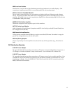
2. Address and Other Settings
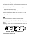
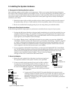
The Access System is made up of smart modules, able to communicate with each other and a control panel
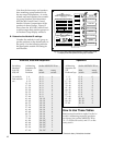
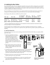
when appropriate. Each “main switching module” (see Figure 14) has a set of rotary switches for assigning
its unique ID or “address.” There are two parts to the address: the “group” number and the “module ID”
number. The group number is the general place a module resides in the system, like a street in a city. The
module ID is the unique number assigned to each module like individual house addresses on one street.
Therefore, each module ID must be unique within the same product group.
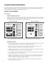
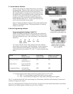
A. Number the Product Groups.
First, determine the portion of the address called the group number. A basic
group address example is shown below. The column to the right shows the
order in which groups appear on the 902 Control Panel. Refer to your
system plan to make a chart like the one below. Number each Product
Group starting with Head Units (always Group 0).
922
958
932
940
942
Figure 14. Main Switching Modules
and location of Group switch. (Model
910D is always Group 0.)
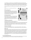
Electronics Speaker Group 902/903 Control
Product Group Product Group Number Panel Display
Head Units 0 1
Processor/EQs 2 2
Front Amplifiers Front Speakers 4 3,4
Rear Amplifiers Rear Speakers 5 5,6
Sub Amplifiers Subwoofers 6 7,8