


54
bUS flashing in EVC window…32
BUS MONITOR LED on 980…32
Buses, explanation of…7
Bypass and EQ group
planning…12
Bypass and programming
switches…18
Bypass, definition of…5
Bypass example wiring
diagram…40
C
Calibration microphone and 902
installation…28
Calibration of speaker volume…8
CD Changer Distribution…10, 11
CD Changers and DC power…23
Choosing switch modules…12
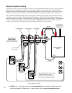
Comparing A/B systems…38
Components of the Access™
System…8
Computer for product selection…7
Connecting the battery…37
Connector polarity…20
Continuous Power Mode…25
Control panel cut-out sizes…28
Control Panel, definition of…5
Control Panel installation…28
Control Panel testing…32
Control Panel to select
products…7
Control Panels…8
Crossover installation…35
Crossover, Model 9A80…10
Crossover switching…12
D
DC Bus wiring diagram…40
DC Eliminator…10
DC Expander Module
installation…19
DC Power Bus and 910D…24
DC Power Distribution Cables…23
Dedicated Crossover…12
Dedicated crossover…12
Delayed Conserve Power
Mode…25
Demonstration Features…38
Deselecting Products with
PSBs…38
Diagnostics for 902/903…32
Diagnostics on 902…8
Digital Audio Adapters…10
DIP switches…18
Display component hookup…34
Duplicate addresses…33
E
EQ and Amplifier Bypass…22
EQ Bypass…46
EQ bypass hookup…23
EQ installation…35
EQ, processor, or crossover
hookup diagram…46
Equal Volume Comparison…8
Equalizer switching…12
EVC…8
EVC Audio Level Module…11
EVC Control Module location…19
Expander Module installation…19
Expander Modules, definition
of…6
Expanders for 902/903…29
Expansion ports…19
F
F-to-Motorola cables…26.
See
also
Antenna Distribution
System
Flashing numeric displays…33
FM Distribution System…26
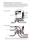
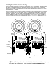
Four-channel amp addressing…49
FRONT HIGH-LEVEL BUS
(bypass hookup)…22
Front/Rear/Sub example wiring
diagram…41
G
Green/white/brown gray cable…20
Ground loop isolator, installation
of…37
Ground loops and 982A…10
H
Hardware installation…3, 19
Head unit DC connection…45
Head unit installation…34
Head unit selector…9
Head unit switching…12
High-level Bus (Speaker Bus)…21
High-Level Bus and bypass from
910D…22
High-Level head unit
connections…45
Hum, troubleshooting…37
I
Identification boxes…18
Indicator LED installation…30
Infrared Control Module…10
Infrared Receiver…11
Install remaining products…37
Installing bus cables…20
K
Kit 17 and FM distribution…10
Kit16 and FM distribution…10
L
Left-Right switch…18
Left-Right switch and Model
932…51
Left/Right Speaker Hookup…51
Lock out on 902…9
LOW VOLTAGE LED…32
Low-capacitance RCA patch
cables…20
Low-level Bus…20
Low-level bus example…7
Low-Level Bus example wiring
diagram…40
Low-Level Bus installation…21
Low-level bypass hookup…23
Low-level signal…7
M
Microphone installation (902)…28
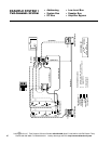
Model 910 Head Unit hookup
diagram…45
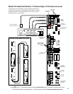
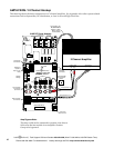
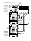
Model 980 2-Channel hookup…47
Model 980 6-Channel
Hookup…47
Module count on 902/903…33
Module, definition of…6
Module ID and 4-channel
amps…49
Module ID and address
settings…15
Module ID settings…16
Mono Speaker Hookup and
addressing…51
Multi-channel displays…12
Multiple speaker pair
selection…38
Multiple speaker pairs in
parallel…18
N
Noise problems…37
Numbering the Product
Groups…15
O
Open or vacant headers…21
Optical Digital Audio Adapters…10