


17
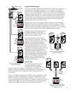
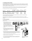
C. Set the Address Switches.
Some Group settings are made at the factory, and cannot
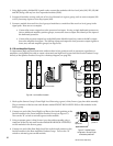
be changed later. Figure 16 shows the first switch module
(Model 910D) in the first Product Group (head units). It
has a default address of Group #0 (set at the factory) and
the Module ID is set to #00 (this lets the system know this
module is connected to the first four products in this
product group). The second 910 would be addressed 01,
and the third module, 02, etc. Always start with zero, not
one, for the first module in any group.
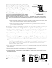
Figure 17 shows the address settings for the fourth module in the
Processor/EQ Product Group. The group default is #2 and the
address is set to #03.
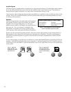
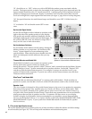
D. Set the Programming Switches.
Programming Switch Settings “S M B T D.”
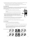
Models 910, 940EZ and 942 have a DIP switch array with small
rocker switches labeled S M B T D (Model 910 has T and D only).
The slide switches are set to “Off” at the factory. The switches are
defined as:
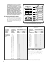
“D” turns on the DC Power Delay feature and works with the
Power Mode switch setting on the 980 module. Use the following
chart to determine switch settings. Set the 980’s “Power Mode”
switch and each main module’s “D” and “T” switch using the chart
below.
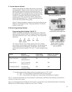
Mode Effect on Power Mode Delay or “D” Switch
Product Groups Switch on 980 on Main Modules
Power Conserve 1 unit ON; ON ON
delayed turn-on
Smart Power Up to 3 units ON; OFF ON
delayed turn-on
Continuous Power All units ON; OFF OFF
no turn-on delay
“T” sets the amount of time delay to allow for product turn-on, if “D” is ON.
“T” - OFF = 3/4 second delay for head units and low power amps.
“T” - ON = 3 second delay for high power amps using switching power supplies.
The “T” switch should be OFF (3/4 second delay) for 910 modules, and ON for 942 modules (3 second turn-
on delay for large power amps).
Also, see “Choosing the Power Mode for Your System” on page 24 for more detailed information on the three
different Power Mode settings available for your Access
™
System.
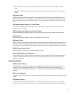
Figure 17. This Model 958 would be the
fourth and last module in group 2
(Processor/EQs), because bypass is ON.
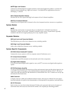
Figure 16. First head unit Module with the
address 0/00 (Group/Module ID).
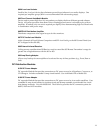
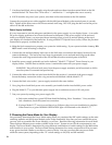
Figure 18. The thirteenth (and last)
module in Group 4 (Front Amps).
Bypass is ON (“B” in programming
switch array SMBTD).
SMBTD
Single Multi- Bypass Time Delay
Stereo Channel