


30
6. Mount the control panel(s) using the four black screws provided. Do not overtighten the screws. Too
much torque during screw insertion can crack the acrylic panel cover.
Installing Product Select Buttons and Product Indicators.
Your system plan may specify using product select buttons (PSBs), and product indicators (LEDs) in conjunc-
tion with a control panel. Some system users prefer to use PSBs as the only method of product selection and
do not have a control panel as part of their demonstration system.
If you have standard square PSBs and/or Product Indicators, install them as follows:
1. Determine where each PSB and Indicator will be located. Most users prefer to locate PSBs close to the
actual product the PSB will select. PSBs are often placed near product information tags or signs that
describe the features and benefits of the products on display. Indicators are also normally placed close to
the components to identify the product(s) currently selected.
• For standard square PSBs: drill a small pilot hole in the panel or surface where each PSB or LED
will be located. Now, drill a
3
⁄4” (19 mm) hole; be precise, a sloppy hole won’t work.
• For LEDs: drill a small pilot hole in the panel or surface where each LED will be located. Now,
drill a
5
⁄16 ” (8 mm) hole; be precise, a sloppy hole won’t work.
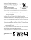
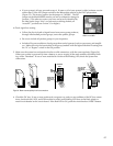
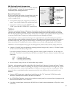
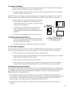
• Disconnect the cable from the PSB or LED, and take note of
the plug polarity. Carefully insert the PSB or LED in the
hole and check the fit. Plug in the PSB cable so that the
cable exits the plug on top for PSBs as shown in Figure 37.
If an LED or PSB does not light up when testing the system
later, simply reverse the polarity of the plug.
Note: if there is no space, or there is some other reason that
holes cannot be drilled for standard PSBs, consider using our
surface mount ZipSwich PSB.
2. Carefully insert the PSB or Indicator in the hole and check the fit.
You may wish to leave the PSB or Indicator mounted in the product
panel, or install them later after your components have been
mounted to their respective product mounting panels.
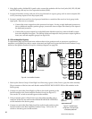
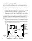
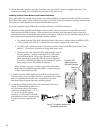
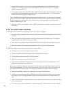
3. Locate the switching module where the component will be con-
nected. Each module has either 4 or 8
two-pin headers above the product
connectors numbered from 1 - 4, or 1
- 8. As you install the display
products, you will connect the PSBs
and Indicators to these headers using
the cable assembly supplied with
each.
PSB/Indicator
headers
Figure 36. PSB
header locations on
942 and 910 modules.
PLUG
RIGHT WRONG
Figure 37. Be careful to maintain PSB
cable polarity at both ends.
PLUG