


29
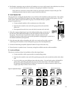
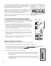
• Plug the calibration microphone into the Microphone jack located on the rear of the 902, using the
extension cable provided, if necessary.
• If your system includes a Model 990 Remote Infrared Receiver, mount the 990 to the ceiling in the
display area and connect the 990 to the header on the rear of the 902 labeled “Aux IR.”
Note: The 903 Control Panel can also be remotely controlled using a 905 IR Remote. A single 905
remote is packaged with the 902, but must be ordered separately for the 903.
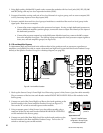
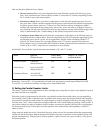
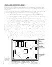
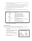
4. Set the Programming Switches on the 902/903.
• Use the following chart to set the 8 programming switches located on the rear of the 902/903
Control Panels (next page).
Switch Function Comments
A Keyboard Click Turn ON for audible key feedback or “beep”
B Demo-Mode Leave OFF. Use only when control panel is not
connected to a system as a “Training Mode”
C Systems ON makes the last unused Product Groupcapable of
Memory storing and recalling 99 system configurations*
D Future Use Spare, leave OFF
E Previous Selection OFF = “C” key is third “flash memory” key
ON = “C” key is toggle between current selection and previous selection
F 902/903 902 = OFF; 903 = ON
G Internal IR Turn OFF when using 990 Remote IR Receiver
H Auxiliary IR Turn ON when using 990 Remote IR Receiver
* If a 904 or 904V Product Group Expander is installed, the last Product Group on the Expander is used for “Systems”
instead of the last Product Group on the 902/903 itself.
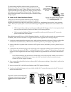
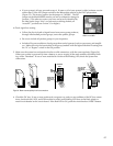
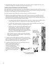
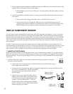
Control Panel Expanders.
All panel openings are 5
1
⁄8” (130 mm) high. Correct cutout widths are shown below. If you have a 904 or
904V Control Panel Expander for use with your 902/903, follow these instructions:
• Cut an opening 11-
3
⁄16” (285 mm) wide by 5
1
⁄8” (130 mm) high to accommodate both the 902/903
and the 904 panels.
• Insert the appropriate slide-in Product Group
labels provided with your control panel into the
product group display windows.
• Connect the 904 ribbon cable to the matching
header on the rear of the 902/903 marked “To
904.”
• Mount the Expander in the opening together with
the 902/903 Control Panel.
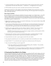
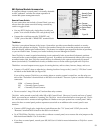
Panel Units Cutout Width
906 or 988CP0 4
1
⁄16” (105 mm)
902 or 903 7” (178 mm)
902/3 + one expander 11
3
⁄16” (285 mm)
902/3 + two expanders 15
3
⁄8” (390 mm)
902/3 + three expanders 19
9
⁄16” (495 mm)
Control Panel Cutout Sizes