


19
3. Installing the System Hardware
A. Designate the Switching Module Locations.
Each switching module controls either 4 or 8 components. Follow your system plan drawing to determine
the location of the switching modules in the display fixture. If you are using factory provided bus cables, you
may wish to connect all the modules that share the system bus with system bus cable, power up the system
on a bench or table, and check the switching modules and control panel logic before actually installing the
modules in your fixture.
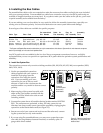
1. Mark the location of the switching modules and any related expander modules near the center of
the products they will serve. Some modules will serve 4 products, others will serve 8 products.
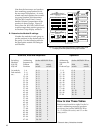
2. Be sure to consider the 2 foot plug spacing if you are using factory pre-made bus cables.
B. Determine Other Module Locations.
In the following installation steps, ignore any references to modules that are not part of your system.
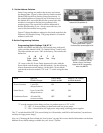
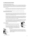
1. Position the 980 System Module in the signal path immediately prior to the first module(s) in your
Amplifier Product Group(s). This position will allow you to pass signals from the output of your
Head Unit or Processor/EQ Product Group to the 980 Module which will then pass the low-level
input signals to your Amplifier Product Group(s).
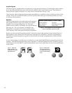
2. If you have “Booster Amps” with high-level inputs in your system, you must use a Model 983
AutoMatch
™
Module to protect the components in your display from damage. The 983 is required
to “match” floating ground output source units with common ground input amplifier units. The
983 should be located near the 940EZ and 940X switching and expander modules that send and
receive signals to and from the booster amps in your display.
3. If your system has a Model 902 Control Panel, you also received a Model 987 EVC Control Mod-
ule. The 987 Module should be positioned just after the 980 System Module in the Low-Level Bus.
When connected, the 980 will receive signals from the 987 Module and send low-level input
signals to your Amplifier Product Group(s). There is a hook up diagram
on Page 4 of the User’s Guide for the 902 Control Panel.
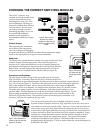
C. Mount the Modules.
1. Mount the main modules first, then plug in and mount signal and
DC expander modules in the system. Use the screws provided.
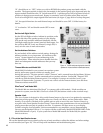
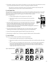
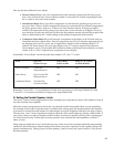
2. Connect an audio signal expander (if any) such as 920X or 940X to
its respective main switching module as shown in Figure 20. It is
critical that the signal expanders be connected to the header port on
the main module labeled “Expansion.” DO NOT plug an audio
signal expander module to the header port labeled
“DC Expansion.”
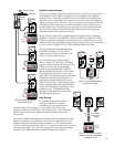
Figure 20. Audio signal
expander connection
920X
920X
942
RIGHT
WRONG
DC Port
Signal
Expander Port
942
RIGHT
WRONG
DC Port
Signal
Expander Port
916X
916X
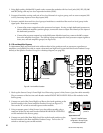
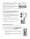
3. Connect each 915X and 916X DC Expander Module to its respective main
switching module and attach with screws provided. Be certain to connect DC
expander modules to the header port on the main module labeled “DC EX-
PANSION.” DO NOT plug a DC expander module to the header port labeled
simply “EXPANSION.”
Figure 21. DC Expander connection