


50
ASD Tech Support USA and Canada: 800-322-8346 (Mon-Fri 8:30 AM to 5:00 PM Eastern Time)
Phone: 859-233-4599 Fax: 859-233-4510 Hookup drawings and FAQ http://www.audioauthority.com
S
993
L+ L– R+ R–
FRONT 942 REAR 942 SUB 942 SHARED AMP
942
942
942
S
S
S
Amplifier
Speaker-Level Output
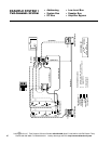
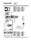
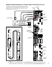
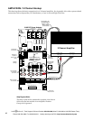
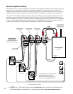
Shared Amplifier Hookup
This diagram shows one stereo amplifier connected to all three Amplifier Product Groups so that it can play in
the front, rear, or sub position. To add three more shared amplifiers, connect each to its own Model 993
adapter, and then connect the adapter to corresponding positions on each 942 module. If some of your amps
will be shared, and some not shared, contact Audio Authority
®
at the phone number below for assistance.
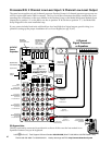
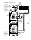
First, mount the switching modules inside your display according to your system plan. Then use the screws
provided to mount each amp’s 993 adapter inside the cabinet or on the back of the amplifier display panel
near the amplifier to be shared. Connect the Input and Output cables from each 942 module to the 993 adapter
as shown. Connect the amplifier to the adapter using the “SHARED AMP” terminals and jacks on the 993.
Contact Audio Authority
®
Technical Service at the phone number below with questions.
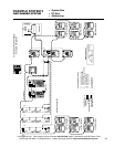
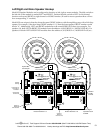
Amplifier
Low-Level Input
Screw Terminal
Speaker-Level Output
Model 993 Amp
Share Adapter
(mount this adapter inside the
display near the shared amp)
Shared Amplifier
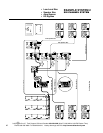
Front Amp Position
Low-Level Inputs
Rear Amp Position
Low-Level Inputs
Sub Amp Position
Low-Level Inputs
Front Amp Position
Switch Module
Rear Amp Position
Switch Module
Sub Amp Position
Switch Module
Position #4
Mounting
Screws
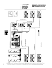
See Appendix A for other system
related connections such as
System Bus, DC distribution, or
Low-Level and High-Level Bus.
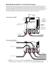
Connect Amplifier’s DC
power to a 916X
expander on any of its
associated 942 modules
(see pp. 22, 43).
Left Right DC Power
High-Level
Output
Note: This drawing is not to scale.