


23
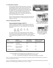
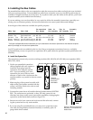
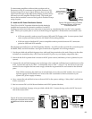
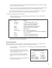
To demonstrate amplifiers without inline products such as
Processors or EQs, it is necessary to bypass the Processor/EQ
Product Group at low-level. Figure 28 shows how to route the
signal from the input of the 958 past the display product connec-
tions and on to the Amplifier Product Group. The fourth posi-
tion on the last module is reserved for bypass in Product Groups
using a bypass.
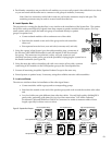
E. Install the DC Power Distribution Cables.
The 915X or 916X DC Expander Modules should already be
installed and connected to electronics modules. Use the EZ
docking port unless more than one connection is required (e.g., ampsharing) then use the 5 wire expander
cable. Check your system plan or use one of the drawings in Appendix A to determine each module’s loca-
tion.
• 915Xs are generally used to power Processor/EQs and CD Changer units. In most systems, head
units are powered directly from the 910 Head Unit Switching Module.
• 916Xs are used to distribute DC power to amplifiers and to provide home run DC connection
points for 910D and 915X modules.
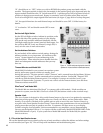
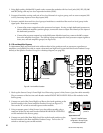
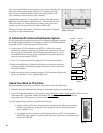
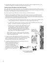
Run the high current DC bus to all 916X Expander Modules. Any 916X can then provide the connection point
for 980EZ, 910D, and 915X modules. See Figure 29 and refer to Appendix A for wiring examples.
1. Use the provided red and black 4 gauge wires with small ring terminals on the ends. Hang on to the other
included wire assemblies; they will be used to furnish DC power to your display components later.
2. Start with the 916X expander that is closest to the DC power source (and battery, if one is planned in your
system).
3. Connect the red and black 4 gauge wires to the large color-coded red and black, brass terminal posts on the
916X. Connect the red wire to “BAT+” and the black wire to “BAT–” using a 7/16" nut driver or open end
wrench. Be sure to tighten the brass nuts snugly so that the ring terminals are well seated on the terminal
posts.
Note: While connecting the initial run of red and black wire to the next 916X module, also connect a
separate 4 gauge red and black set of wires to the 916X’s terminals for final connection to your
system’s DC power supply or battery.
4. Now, connect the red and black wires to the next 916X in the system, making a “daisy-chain” until the last
916X is connected.
5. Run low-current DC to all 910 Source Modules and 915X Expander Modules.
6. Use the red and black 14 gauge wires provided with the 910. Connect the ring ends to the DC bus termi-
nals of the nearest 916X.
Low-level
signals to
980 module.
Figure 28. EQ bypass bus wiring on last 958 in
the Processor/EQ group. No EQ can be
connected to position #4.
958
Low-level signal from
Source Bus or previous
958 module.
Bypass Switch ON
916X
2/77
Power
Source
958
942942
916X
915X
14 Gauge Red/Black
8 Gauge Black
8 Gauge Red
Figure 29. DC trunk lines connect 916X modules
to each other and the power source; 915X, 910D,
and 980EZ branch from the nearest available
916X.