


26
975
To Head
Units’
Antenna
Inputs
Antenna
FM Amp
Changer
Changer
4-Way Tap
Figure 31.
Termination
Plug
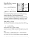
The Access System allows you to program up to 4 pairs of speakers to
play in the same product group. However, we strongly encourage
you to leave the default setting at 2 pairs per group, unless you’re
very confident of each and every amp’s stability.
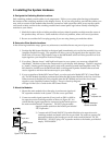
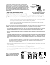
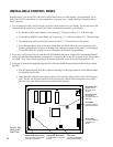
Immediately beneath the “Power Mode” switch on the 980 are three
additional switches labeled “Speaker Limit.” The switches are set to
OFF at the factory. To change the factory setting, turn on the limit
number switch you want. Leave the other switches OFF.
Example: Turning limit number 3 ON allows three pairs of speakers
per group to play simultaneously.
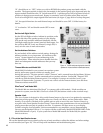
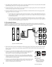
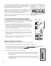
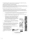
H. Install the RF Antenna Distribution System.
If your system plan included provisions for an Antenna Distribution System,
or includes RF distribution for CD changers, install the 975 FM Distribution
Amp and a KIT17 for each group of four head units.
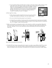
A. Unpack items 975 FM Amplifier and KIT17(s). Follow the enclosed
instructions completely, making sure that the coax cable used to connect
the 4 way taps is not kinked or bent during the hookup process. If you
need additional instructions, please contact the factory and ask that we
send you our part number 752-139.
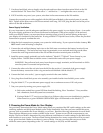
C. Use a 7/16" open-end wrench to tighten all F-connector terminations.
D. Make certain that the F-to-Motorola cables are not allowed to touch the
switching modules. The Motorola plug could cause a short if allowed to
touch the modules.
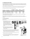
E. Make sure that you have inserted the proper F-59 Termination Plug in the
last 4 way Tap Block’s “Out” position (Figure 31).
Check Your Work to This Point.
Before continuing any further, it would be a good idea to check the following:
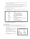
1. Check the Group and Module ID settings on all modules against your system plan.
2. Check the Expander modules in the system to insure that audio signal expanders (920X, 940X if any) are
connected to the “Expander” header and that the DC expander modules (915X, 916X) are
connected to the “DC Expansion” header on their main modules.
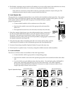
3. Check programming switches, especially the following:
• Bypass switch is ON where a bus has been connected to the 4th product position
on the last module in a group that can be bypassed (such as processors, passive
EQs, amplifiers, etc.).
• Left–Right switch set correctly on 932 Speaker Selectors; LEFT for left speakers,
RIGHT for right speakers. In special cases, like mono subwoofers, set switch on the
single 932 to RIGHT.
Figure 30. Detail of 980EZ Module showing
speaker limit switches.
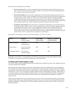
Figure 32.