


28
INSTALLING A CONTROL PANEL
Skip this step if you do not have a 902, 903 or 906 Control Panel, or if the display is pre-assembled. If you
have a 902 or 903 Control Panel, it is accompanied by a separate User’s Guide which you should locate for
future reference.
1. Cut an opening for the Control Panel if you wish to flush mount it in your display. You can also use a 989
Enclosure Kit to house your Control Panel which can be shelf-mounted in your display.
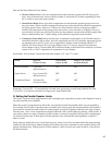
• For the 902 or 903 Control Panels, cut an opening 7” (178 mm) wide by 5-
1
⁄8” (130 mm) high.
• For the 906 or 988CP0 Control Panel, cut an opening 4 -
1
⁄16” (105 mm) wide by 5-
1
⁄8” (130 mm) high.
• Use the panel to mark screw hole locations and drill
7
⁄64” (2.5 mm) holes for the screws.
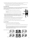
• Insert the appropriate slide-in Product Group labels provided with your control panel into the
product group display windows to identify each component group on the panel. Consult page 6
of your 902/903 User’s Guide for more information on Product Group labeling.
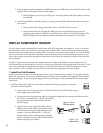
2. If you have a 902 Control Panel, locate the 987 EVC Module that came with the 902. You installed the 987
earlier near the 980 System Module (see page 19). Connect the 902 to the 987 using the 10-pin ribbon cable
provided. Note: You will still need access to the rear of the 902, so do not mount it permanently yet.
3. Using the 10 foot cables supplied, plug the 902 or 903 into the 980 System Module at the header marked
902/903.
• The 987 should already have RCA cables connecting it in the signal path out of the 980 that feeds
the amplifier input buses.
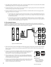
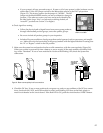
• Hang the 902’s calibration microphone about 1 foot from the ceiling at the center of the listening
area. The mic can be flush-mounted in the ceiling tiles, if desired, but performance may suffer.
The mic is an omni-directional electret condenser microphone.
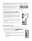
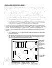
A
B
C
D
E
F
G
H
AUX IR
MICROPHONE
TO 904
ON
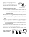
ProductGroup Expansion Port
34-Pin connector for Model 904
ProductGroup Expander
Configuration DIP Switches
to enable/disable control panel
features
3-Pin Header
connection for Model 990
Auxiliary Infrared Receiver
10-Pin Header
connection for Model
987 Audio Level
Module
6-Pin Header
connection for Model
980 System Module
Microphone Jack
Connect 902's
microphone extension
cable here
RS-232 Serial Port
Modular Jack for
connection PC or
modem
RS-232
Figure 35. Rear
view of the 902
Control Panel.