


22
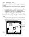
942
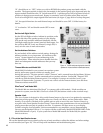
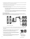
Last 942 in Front Amp Group
B
Switch
ON
Speaker Bus
Bypass cable from 910
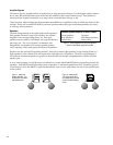
Figure 27. Amplifier Bypass
configuration. No amp may be
connected to position #4.
An amp in
position #1
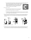
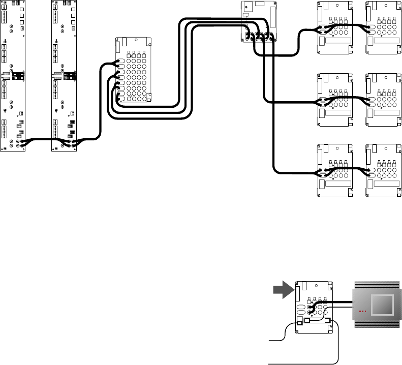
1. Using high-quality shielded RCA patch cords, connect the modules with low-level jacks (910, 922, 958, 980
and 942) along with any low-level expander modules (920X).
2. Connect all modules serving each pair of low-level channels in a given group, such as source outputs (910
or 922), front amp inputs or rear amp inputs (942).
3. Connect a module from each low-level group of modules to a module of the next low-level group in the
signal path. Here are two examples:
• Connect the source output bus to the processor bus input; if using a single dedicated processor to
derive additional amplifier product groups, connect the source output bus directly to the input of
the dedicated processor.
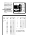
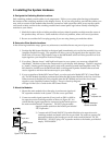
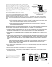
• Connect the processor output bus to the 980 System Module input bus; connect the 980’s output
bus to the amplifier bus input. The 980 has inputs and outputs to feed processor output signals to
front, rear, and sub amplifier groups (see Figure 26).
D. EQ and Amplifier Bypass.
To demonstrate high powered head units without other in-line products such as processors, equalizers or
amplifiers, use Speaker Bus cable to create a front and rear high-level bypass from the Source Product Group
directly to the Speaker Product Group (for a hookup diagram, see page 40).
1. Hook up the Source Group’s Front High-Level Bus using a green/white/brown/gray bus cable assembly.
Plug a connector of the bus into each header marked FRONT HIGH-LEVEL BUS on 910 modules in the
Source group.
2. Connect one end of the Front High-Level Bus to the fourth position on the
last 942 module in the Front Amplifier Product Group (see Figure 27).
Turn on the “B” switch to activate bypass on that module.
3. Using a separate green/white/brown/gray bus cable assembly, plug a
connector of the bus into each header marked REAR HIGH-LEVEL BUS
on 910 modules in the Source group.
4. Connect one end of the Rear High-Level Bus to the fourth position on the
last 942 module in the Rear Amplifier Product Group. Turn on the “B”
switch to activate bypass on that module.
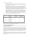
958
942
942
980
942
942
942
942
910910
Front
Low-Level
Bus
Rear
Low-Level
Bus
Sub
Low-Level
Bus
Source Low-Level Bus
Figure 26. Low-Level Bus Illustration.