


20
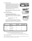
4. Installing the Bus Cables
Pre-assembled bus cables or the raw materials to make the necessary bus cables on the job site were included
with your system purchase. Pre-assembled bus cables have connectors every two feet (RCA patch cords are
available in lengths from three to twenty feet). If you plan to make your bus cables on the job site, you’ll need
a special assembly tool available from the factory.
If you are making your own bus cables, be very careful to follow the assembly instructions, especially con-
cerning wire to connector polarity. Incorrect bus fabrication can cause system failure and damage!
Several types of bus cables are available for specific purposes:
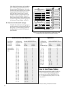
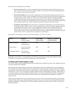
Pre-assembled Cable for Plug for Assembly
Cable Type Color Code Part Number Site Assembly Site Assembly Tool
System Bus yellow/red/blue/black 802-307 871-055 916-0470 762-011
Speaker Bus green/white/brown gray 802-186 871-045 904-172 762-009
Low-level Bus RCA patch cords 801-018 to 801-023 EX2, EX1 SGRCA 762-006
System extension* yellow/red/blue/black 802-323 871-055 916-0470 762-011
Speaker extension* green/white/brown/gray 802-309 871-045 904-172 762-009
* The System and Speaker Bus extension cables allow you to join remote sections of the Access
™
System with the main electronic component
section of your display, as in the case of rear speaker towers.
Any RCA patch cords are suitable for the low level bus or component connections; however, we highly
recommend that you use our special low-capacitance RCA patch cables for optimum system performance and
reliability.
A. Install the System Bus
The system bus connects only to main switching modules (910, 920, 958, 942, 932, 940), not expanders (920X,
940X, 915X, 916X).
1. Use the pre-assembled system bus
cables supplied with your system or
install the 4 pin plugs onto the
system bus wire using the special
tool. If you are making your own
system bus, be sure to leave a small
amount of slack in the wire between the
modules and be very careful to observe correct
polarity.
2. Mate one plug of the system bus cable with
either of the 4 pin headers marked with the
yellow/red/blue/black color code on each
switching module.
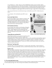
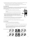
3. Connect the system bus to all modules having headers marked SYSTEM
BUS. The connectors are polarized, so they will only connect in one
direction, but always make sure to prevent the possibility of plugging the
system bus to the header backwards (see Figure 23).
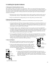
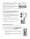
4. Start at one end of your system and work toward the other end, connect-
ing the system bus to every main module.
5. If you are using Pre-assembled buses, you may use a system bus exten-
sion cable for long distances between modules, or carefully splice 18
gauge cable where needed.
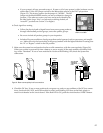
SYSTEM
BUS
YELLOW WIRE
ALWAYS ON
THIS SIDE OF
PLUG
GROUP
D
ULE ID
BLACK
BLUE
RED
YELLOW
Figure 23. Observe correct System
Bus polarity. It is fine to leave one
header unused.
922
958
932 940
942
910
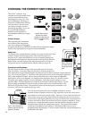
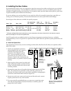
Figure 22.
Connect System
Bus to every
Main Module.