


27
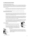
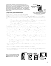
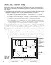
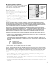
• If your system is all new, proceed to step 4. If some or all of your system is older (software version
earlier than 3.2) the SST jumper switch on the 980 module must be in the FAST pin position
(Figure 33). The factory position for the jumper is “NORM.” The SST
jumper on the Model 980EZ must be cut and re-soldered to change its
position. (The software version you have can be easily identified by
the label on the large “chip” on each main switching module; all
AccessEZ
™
products are version 3.3 or higher).
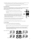
4. Check signal bus routing.
• Follow the physical path of signal buses from source group products,
through intermediate product groups, out to the speaker groups.
• Be sure to include all product groups in your inspection.
• Include all bypass conditions; check groups that can be bypassed, such as processors and amplifi-
ers. Make sure only the last module in the group (module with the highest Module ID setting) has
the “B” or “Bypass” switch in the ON position.
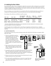
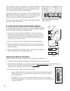
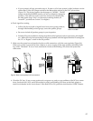
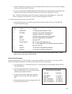
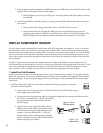
5. Make sure the system bus and speaker bus have solid connections, with the correct polarity (Figure 34).
When your system is powered up from a battery or power supply, all the main modules should be blink-
ing, with a “heartbeat.” If one or more modules do not show the blinking LED, check the System Bus
connections.
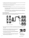
6. Check the DC bus. If one or more products do not power up, and you are confident of the DC bus connec-
tions, check each 910, 915X, and 916X module for a Red, non-blinking LED close to the black plastic or
metal circuit breaker on the circuit board. If the Red LED is ON, push the circuit breaker’s RESET button.
SYSTEM
BUS
YELLOW WIRE
ALWAYS ON
THIS SIDE OF
PLUG
GROUP
D
ULE ID
BLACK
BLUE
RED
YELLOW
GREEN WIRE
ALWAYS ON
THIS SIDE OF
PLUG
SPEAKER
BUS
GRAY
BROWN
WHITE
GREEN
RIGHT WRONG
PLUG
Figure 33. The “SST jumper
switch” on the 980A.
Figure 34. Observe correct polarity for all bus connections.