


34
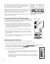
3. Select a speaker position using the test PSB, then move the PSB to the same module location on the
opposite side of the speaker section of the display.
• The PSB lights up as soon as you plug it in, showing both left and right speaker positions
are selected.
4. Attach the test PSB to a second speaker in a group, press the PSB and hold the button for at least
one second.
• If the speaker limit setting on the 980 is set to 1, the PSB will not come on.
• If the speaker limit is 2 or higher, the PSB will come on in both the first and second
speaker position (factory default is 2, with 980 limit switches all in the OFF position). The
902/903 displays the two speaker positions alternately in the speaker’s PG window.
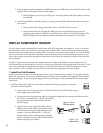
DISPLAY COMPONENT HOOKUP
It is now time to begin installing the car audio head units, EQs, amplifiers and speakers. If you’ve followed
the instructions so far, you will have a working system in short order. This section assumes that the compo-
nents have been mounted onto removable panels or onto the front portion of your fixture. You will obviously
need to connect the wires from the components to the switching system and DC distribution system, so you
may wish to map out a plan for that process that allows easy access to the modules from the front or the rear
of your display.
Usually, it works out best to mount the components to be located at the bottom of your display first, and
work toward the top of the display so you can avoid masses of hookup wire hanging down from above. Take
your time mounting the components and be sure to save their boxes and accessories, so that you can offer
your customer a new or almost new unit when you later take the component out of the display.
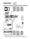
1. Install the First Products
Install one product in each of several groups in order to get a simple system running. For example, install a
head unit, a processor (if any), a two-channel amp, and a pair of front speakers (see Appendix B for detailed
hookup drawings). Leave your power supply ON and your battery, if any, connected, but be careful using
metal tools.
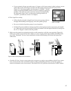
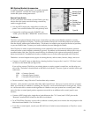
A. Connect a head unit’s high/low-level audio outputs and DC power inputs to a product
position on the 910 Module.
• Connect the low-level output to the red (R) and white (L) female RCA jacks using
short, high quality patch cables.
• Connect the unit’s front and rear high-level (speaker) outputs to the two terminal blocks next to
the “Power” terminal block. Observe the polarity
legend printed on the circuit board under the
terminal plugs.
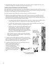
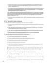
• Connect the two-pin plug of the PSB’s cable, if
PSBs are used, to the small 2 pin headers on the
910 circuit board at the corresponding product
position. Press the PSB into the
3
⁄4” hole you
drilled earlier in the mounting panel or display
fixture. Plug the connector into the PSB with the
cable exiting on top as shown.
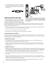
PLUG
RIGHT WRONG
Figure 40. Correct
PSB cable polarity.
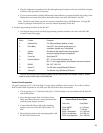
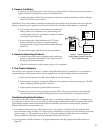
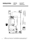
1 2 3 4
L+ L– R+ R–
High-Level
PLUG
PSB
POWER
IGN
BAT
GND
Figure 41. DC
power terminal