


24
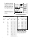
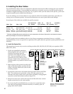
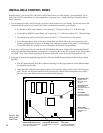
7. Cut the red and black wires to length, strip the ends and insert them into the terminal block on the 910
module labeled “DC Power Bus.” Wire red to “+” and black to “–” and tighten the screws securely.
8. If 915X modules are part of your system, wire them in the same manner as the 910 modules.
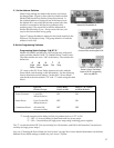
Connect the pre-made power cable supplied with the 980 System Module to the terminal posts of a nearby
916X. Tighten all the brass nuts on 916X bus terminals until snug. DO NOT plug the other end of the power
cable in to the 980 at this time.
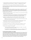
Power Supply Ventilation.
It is very important to provide adequate ventilation for the power supply in your display fixture. A car audio
DC power supply generates a lot of heat which must be dissipated. If the power supply will be enclosed
inside your display fixture, you must provide an incoming source of cool air and an opening at the top of
your display for ventilation of the heated air. If using a Model 277 Hybrid Power Source, follow the provided
instructions to properly ventilate the unit.
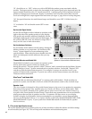
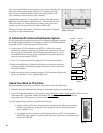
A. Make the final connections to prepare your system for initial testing. If your system includes a battery, DO
NOT install it until all testing is complete.
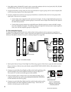
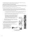
1. Connect the red and black battery lead wires to the 916X most convenient to the battery location (do not
connect the battery). The lead wires have large ring terminals on one end and small rings on the other.
Connect the small ring terminal ends of the red and black leads to terminal posts of the 916X.
2. Install the power supply, preferably an Audio Authority
®
Model 2/77 Hybrid
™
Power Source in your
display fixture. Take the time to read the owner’s manual that came with your power supply.
WARNING: Keep all metal tools away from the power supply terminals, and all terminals on 916Xs
once the system is connected and powered up.
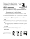
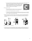
3. Connect the other end of the red wire from the 916X to the positive (+) terminal of the power supply.
Secure the battery connection with a wing-nut and stud furnished with the Model 2/77.
4. Connect the black wire to the (–) power supply terminal in the same fashion.
5. Now, plug the red and black power wire assembly you installed earlier into the 980’s power socket.
6. Plug the Model 2/77 or your alternate power supply into a continuous source of 120 volt power.
7. Test your system by turning your power supply ON.
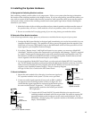
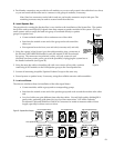
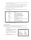
A. Each main module has a green LED that should be flashing, like a “heartbeat.” If any modules
lack a heartbeat, check the system bus connection.
B. If using a Model 2/77, turn it on and leave it on 24 hours a day once your installation is complete.
When turned on, a green NORMAL OPERATION light will illuminate on the Model 2/77.
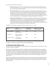
F. Choosing the Power Mode for Your Display.
You previously determined the Power Mode setting when you completed the DIP switch settings on the main
switching modules and 980 System Module earlier in the installation. Now that you have reached this point,
you may wish to reconsider the Power Mode(s) you will use. Read the following information for more detail.
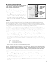
There are three different power modes available in the Access
™
System to turn ON the components in your
display. The Power Mode is determined by using different combinations of switch settings on the 980 and the
main modules in your system. The Power Mode setting determines how many components will be powered
at any given time and whether or not there is a turn-on delay. You may use more than one power mode
within the same system, depending on the “D” switch settings on 910, 958, and 942 modules.