


160 Barco - RHDM-1701 - User manual
Video signal processing
• Extended Gamma: This option is an extension of the “pure gamma” OETF to headroom and
footroom, with the same intent as xvYCC.
In addition to these possible OETFs, the user can also select the gamma exponent
γ
(ranging from
1.0 to 3.0, with a default value of 2.35 as per EBU Tech.3320). This gamma exponent can be
understood as the resulting
“effective gamma” of the display.
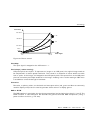
The simplest function is the “pure gamma”, where L-L
0
~V
γ
. But because of differences between CRT
and LCD technology, using a pure gamma function in LCDs will result in crushed blacks. The users
would need to increase the background offset (black level) in order to set up the monitor according
to the Pluge pattern. But this increases the black level and decreases the available contrast range of
the display.
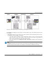
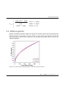
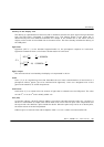
Therefore the RHDM uses the following OETF concept:
• Invert the encoding equations (Rec.709, xvYCC, sRGB or SMPTE240M) exactly, preserving the
“linear toe”.
• Make sure that the “rendering intent” is preserved, which means that the resulting effective
gamma is equal to the gamma selected by the user (default 2.35 as per EBU 3320 recommenda-
tion).
• Take the limited LCD contrast into account so that the dark levels are perceptually discernable.
This implementation avoids crushing of blacks that would be exhibited by using a pure gamma
function and eliminates the need to set the video offset. The rendering intent used in the display
unit ensures that at a luminance level of 100 cd/m
2
the lowest step in the Pluge pattern are just
noticeable.
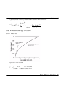
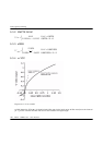
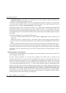
Detailed example: Pure gamma
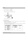
The OETF shown below describes the translation of the electric signal to the video drive level. This
formula applies for each color.
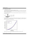
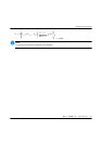
The light output (luminance) Y
i
for each color (i=R,G,B) of an ideal screen is related to the
maximum light output Y
i
max
(for each color) multiplied by the gamma corrected color factor. The
color factor is the input voltage V
i
in
(or Y
i
’) weighted by the reference white voltage V
i
inrw
. The LCD
screen is not able to suppress all the light coming from the backlight trays. There is still some light
(Y
i
0
) emitted by the LCD screen when V
i
in
= 0. This remnant emission of light is called display black
level. The video gain G is a way to enhance the light output of the image, without influencing the
black level of the image. The gain is expressed in the formula in %. Background B is the user
control that allows the user to shift the black level (e.g. to see the content in dark regions of the
image better) of the image. Picture P is the user control that drives the power of the backlights.
From this equation you can readily see that Picture has an influence on the black level that is set by
the Background and the dark offset of the LCD panel.