


NX-800/800H
10
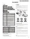
■
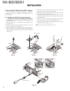
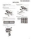
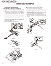
Connect the KRK-10 main panel to the rear
panel with the cable
8. Insert one 14-pin connector of the cable (E30-7514-15)
into the connector (CN3) of the interface unit (A/2) of the
main panel. (
!1
)
Note: Insert the connector that has a sticker onto the
cable to the connector of the main panel.
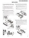
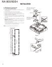
9. Secure the cable bush on the main panel and fi t the wa-
terproof packing (orange) (
!2
) securely over top.
10. Install the molded cover (
!3
) over the connector on the
main panel and secure it with two screws (
!4
).
11. Insert the other 14-pin connector of the cable into the
connector (CN4) of the interface unit (B/2) of the rear
panel. (
!5
)
12. Secure the cable bush on the rear panel and fi t the wa-
terproof packing (orange) (
!6
) securely over top.
13. Install the molded cover (
!7
) over the connector on the
rear panel and secure it with two screws (
!8
).
Note: A cable can be connected from the left side as shown
in the Figure 3-5 or from right side.
However, the 14-pin connector must be connected to cor-
rect direction.
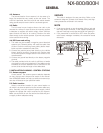
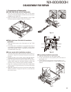
4. Voice Guide & Storage Unit
(VGS-1: Option)
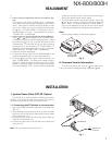
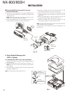
4-1. Installing the VGS-1 unit in the transceiver
1. Remove the cabinet, top packing and shielding plate of
the transceiver.
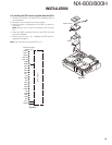
2. Attach two cushions to VGS-1 as shown in Figure 4. (
q
)
Note: Be sure not to cover the connector with the bot-
tom cushion.
3. Insert the VGS-1 connector (CN1) into the TX-RX unit (A/2)
connector (CN595). (
w
)
Note: You must setup using the KPG-111D.
CN4
CN3
(Right side)
KRK-10
rear panel
KRK-10
main panel
Sticker
Sticker
Fig. 3-5
CN1
CN595
:
@
Cushion
(G13-1994-04)
20 x 30 x 12 mm
Cushion
(G13-1992-04)
21 x 21 x 2.5 mm
VGS-1
Fig. 4
INSTALLATION